
Circuit Diagram
Index 934
OPERATIONAL_AMPLIFIERS
Published:2009/7/8 22:12:00 Author:May
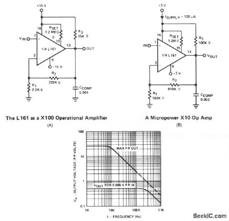
This is a single gain-of-100 amplifier with a gain-bandwidth product of 20 MHz! The primary limitation in the performance is the low slew rate (0.3 V/μs) imposed by IOH charging CCOMP. The effects of slew rate and compensation are shown. A lower gain amplifier requires a larger CCOMP, which in turn further reduces slew rate. For this reason, it might actually be advantageous in certain areas to lower the gain by placing a resistive divider at the input rather than raising RI. Figure 66-1B shows a 700-μW, X10 op amp whose slew rate is 0.02 V/μs and is 3 dB down at 100 kHz. (View)
View full Circuit Diagram | Comments | Reading(719)
BEACON_TRANSMITTER
Published:2009/7/8 22:10:00 Author:May

This transmitter can be used for transmitter hunts, for remote key finding, or for radio telemetry in model rockets. It can be tuned to the two meter band or other VHF bands by charging C1 and L1. L1 is four turns of #20 enameled wire airwound, 0.25 inch in diameter (use a drill bit), 0.2 inch long, centertapped. The antenna can be 18 inches of any type of wire. IC2 functions as an audio oscillator that is turned on and off by IC1 about once per second. The range of the transmitter is several hundred yards.
(View)
View full Circuit Diagram | Comments | Reading(1118)
D_C_D_C_CONVERTER_USES_10_KC_MVBR
Published:2009/7/21 4:38:00 Author:Jessie

Free-running mvbr and square-hysteresis-loop transformer together fire Q1 and Q2 alternately to give constant frequency independent of changes in input voltage, while varying pulse width to give voltage regulation. Short-circuits cannot damage power supply. -E. Josephson, Satellite Power Supply has Variable Pulse Width, Electronics, 35:8, p 47-49. (View)
View full Circuit Diagram | Comments | Reading(787)
LM1871 (electronic toys and model cars) wireless remote control launch coding circuit
Published:2011/8/2 3:43:00 Author:TaoXi | Keyword: electronic toys, model cars, wireless, remote control, launch, coding circuit
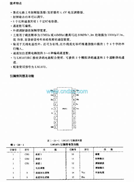
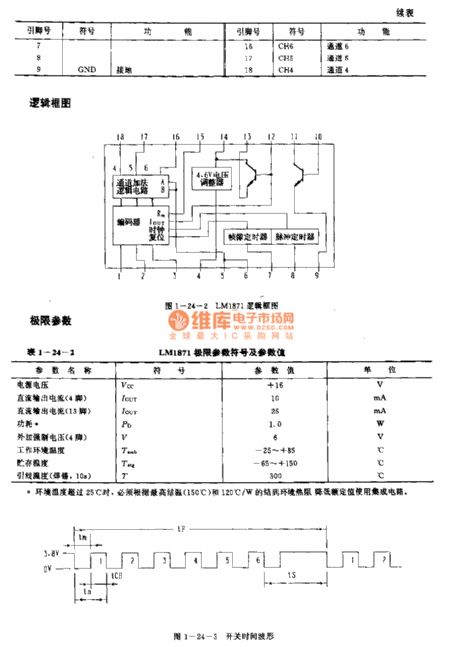
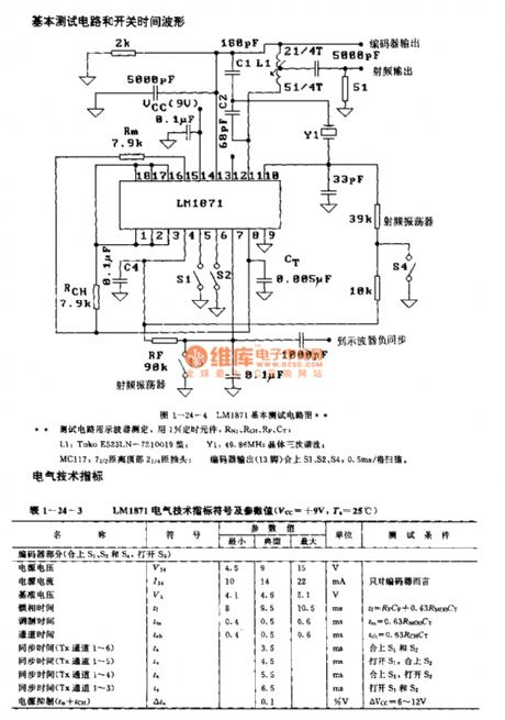

The LM1871 is designed as the wireless remote control launch coding circuit that can be used in the electronic toys and model cars. The internal circuit is composed of the channel addition logic circuit, the 4.6V voltage regulator, the encoder, the frame-picture timer and the pulse timer.
FeaturesThe IC has the radio frequency oscillator/transmitter and the 4.6V voltage regulator.The RF output power is adjustable.The six proportion channels use the same timing capacitor.The channel number is programmable. The external modulator controls the frequency band width.It can be used in the low power, non-speech signal and unauthorized communication devices with the carrier frequency of 27MHz or 49MHz and the 3m field strength of 10000uV/m.
(View)
View full Circuit Diagram | Comments | Reading(1978)
_HIGH_Q_NOTCH_FILTER
Published:2009/7/8 22:10:00 Author:May


This circuit shows a twin-T network connected to an LM102 to form a high-Q, 60-Hz notch filter. The junction of R3 and C3 which is normally connected to ground, is bootstrapped to the output of the follower.Because the output of the follower is a very low impedance, neither the depth nor the frequency of the notch change ; however, the Q is raised in proportion to the amount of signal fed back to R3 and C3. Shown is the response of a normal twin-T and the response with the follower added.
(View)
View full Circuit Diagram | Comments | Reading(885)
Modified_scale_factor_and_offset_circuit
Published:2009/7/21 4:36:00 Author:Jessie

Modified scale factor and offset circuit (courtesy Analog Devices, Inc.). (View)
View full Circuit Diagram | Comments | Reading(494)
TWIN_T_NOITCH_FILTER
Published:2009/7/8 22:09:00 Author:May

This filter is used to reject or block a frequency or band of frequencies. These filters are often designed into audio and instrumentation systems to eliminate a single frequency, such as 60 Hz. Commercial grade components with 5%-1070 tolerance produce a null depth of at least 30 to 40 dB. When a twin-T network is combined with a TL081 op amp in a circuit, an active filter can be implemented. The added resistor capacitor network, R2 and C2, work effectively in parallel with the original twin-T network, on the input of the filter. These networks set the Q of the filter. The op amp is basically connected as a unity-gain voltage follower. The Q is found from:
R2 C1 Q = — = — 1R2 C2For a 60-Hz notch filter with a @ of 5, it is usually best to pick the C1 capacitor value and calculate the resistor R1. Let C1 = 0.22 μF. Then:
R1 = 12 KΩ R1 = 120 KΩ C2 = 0.047/μF
Standard 5% resistors and 10% capacitors produce a notch depth of about 40 dB, as shown in the frequency response curve.
(View)
View full Circuit Diagram | Comments | Reading(889)
WIRELESS_FM_MICROPHONE
Published:2009/7/8 22:08:00 Author:May


Transistor Q1 acts as an amplifier for condenser microphone MIC1. The output of Q1 is applied to the base of transistor Q2 through a 4.7- μF capacitor. C2 and L1 form an LC tank circuit, which is used to set the frequency at which the transmitter operates. Coil L1 is a variable inductor, centered a bit below 1 μH, that is used to adjust the modulating frequency of the circuit. Capacitors C1 and C2 are 4.7 pF units. A lower value can be used to raise the circuit's operating frequency. The microphone and Q1 provide a vary-ing voltage at the base of Q2, with the output of Q2 applied to the LC tank circuit. That causes a modulating action in the tank circuit that, when applied to the antenna, a short piece of wire 6- to 8-inches long, will provide a good, clear FM signal somewhere in the range of 88 to 95 MHz with a range of about 100 feet. (View)
View full Circuit Diagram | Comments | Reading(911)
OPAM_PICOAMMETER
Published:2009/7/8 22:05:00 Author:May

Current-to-voltage converter connection for CA3160 and CA31400 bipolar MOS opamps provides full-scale meter deflection for ±3 pA CA3160 is operated in guarded mode to reduce leakage current.CA3140 provides gain of 100 for driving zerocenter microammeter. With suitable switching, full-scale current ranges of 3 pA to 1 nA can be handled with single 10.000-megohm resistor in overall feedback path.-″Circuit Ideas for RCALinear ICs″RCA Solid State Division Someville,NJ,977,ρ 14. (View)
View full Circuit Diagram | Comments | Reading(1154)
IJC7462M (TV) infrared remote control launch circuit
Published:2011/8/2 3:53:00 Author:TaoXi | Keyword: TV, infrared, remote control, launch circuit


The IJC7462M is designed as the infrared remote control launch circuit that can be used in the TV application. The internal circuit is composed of the button output timing signal generator circuit, the button control signal input circuit, the button data register, the user code register, the oscillating circuit, the frequeny divider, the decoder.
Features
The CMOS large scale integrated circuit.In the standby state, the current consumption is lower than 10uA.It has the oscillating circuit, you can add the quartz resonator to form the clock oscillator.20-pin dual-row DIP plastic package.The matching model is CX20106A.
(View)
View full Circuit Diagram | Comments | Reading(2968)
TV_sound_channel_with_2_watt_output_using_an_ECG742
Published:2009/7/21 4:35:00 Author:Jessie

TV sound channel with 2-watt output using an ECG742. Supply voltage is from 18 to 27 volts. The chip is a 16-pin DiP. The circuitcan be connected toan 8-ohm load and still provide the 2-watt output (courtesy GTE Sylvania Incorporated). (View)
View full Circuit Diagram | Comments | Reading(784)
A Circuit of Crystal Switched Transistor Bridge Direct Current and Servo Electronic Machines
Published:2011/8/1 2:15:00 Author:Zoey | Keyword: Switched, Crystal, Transistor Bridge, Direct Current , Servo Electronic Machines

Transistors of this bridge circuit only works in saturated and ceased state. It has a better regular linearity bridge than usual ones, and it can achieve dynamic brakeif needs to. Servoeffect ofthis circuit is controlled by thevoltage signal margin ofU1 andU2.
when 0≤U1-U2≤U1RA/(RA+RB) or0≤U2-U1≤U2RA/(RA+RB),
both comparator will input highlevel, D1and D2 will cease to work, D3 and D4 will conduct, making T1 and T2 cease to work,T3 and T4 be saturated, the motor will not be able torotate without voltage.
When U1-U2>RAU1/(RA+RB),T3 and T2 will turn to be saturated and will conduct, the voltage will be added on the motor.
When U2-U1>RAU2/(RA+RB),T1 and T4 will turn to be saturated and will conduct, the motor will rotate reversely. (View)
View full Circuit Diagram | Comments | Reading(1132)
7_KV_CRT_SUPPLY
Published:2009/7/21 4:35:00 Author:Jessie
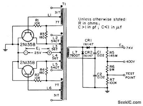
Provides high-voltage source for screen grid and final anode of 5 to 12-inch magnetic-deflection cathode-ray tubes in equipment having full or partial transistorization. Full-wave d-c to d-c converter, with transistor load connected between voltage source and emitter, permits attaching collectors to grounded or chassis-connected heat sink.-NBS, Handbook Preferred Circuits Navy Aeronautical Electronic Equipment, Vol. II, Semiconductor Device Circuits, PSC 6 (originally PC 202), p 6-2. (View)
View full Circuit Diagram | Comments | Reading(826)
PHOTOMULTIPILIER_SUPPLY
Published:2009/7/21 4:46:00 Author:Jessie
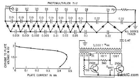
String of Cockcroft-Walton voltage doublers multiplies a-c output voltage of blocking oscillator to step up battery voltage to required 2 kv. Regulation is reasonably constant up to 0.4 ma plate current. –R. P. Rufer, Battery Powered Converter Runs Multiplier Phototube, Electronics, 33:28, p 51. (View)
View full Circuit Diagram | Comments | Reading(806)
KA2310 (toy) wireless remote control launch control regulation circuit
Published:2011/8/2 4:00:00 Author:TaoXi | Keyword: toy, wireless, remote control, launch, control, regulation circuit


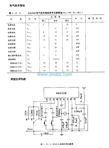
The KA2310 is designed as the wireless remote control launch control regulation circuit that can be used in the toy application. The internal circuit is composed of the pulse generator, the pulse width controller, the transmitting signal oscillator,the modulator, the high frequency amplifier and the automatic power switch. This device is in the 9-pin SIP package. The matching model is KA2309.
(View)
View full Circuit Diagram | Comments | Reading(2305)
LOW_FREQUENCY_TRANSMITTER
Published:2009/7/8 22:04:00 Author:May
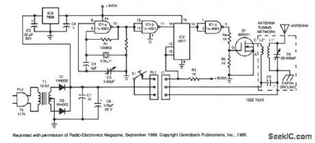
The crystal oscillator, which uses two sections of IC1, a 4001 quad 2-input NOR gate, is a standard and reliable design. The oscillator's 1.85-MHz, square-wave output feeds IC2, a 4017 divide-by-10 counter. The count enable and reset terminals, pins 13 and 15, are normally held high by resistor R3, and the counter is activated by bringing those pins low by closing telegraph key S1-an arrangement that guarantees that the final state of IC2 pin 12 is always high. The high on IC2 pin 12 is inverted by a third section of the 4001, IC1c, to prevent dc current flow through power amplifier Q1 during key-up periods. (View)
View full Circuit Diagram | Comments | Reading(1703)
Triac_control_circuit_using_an_ECG776_zero_voltage_switch_IC
Published:2009/7/21 4:48:00 Author:Jessie
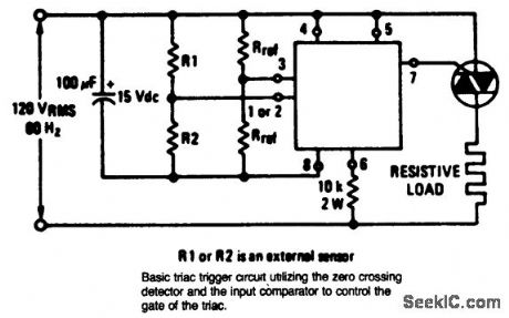
Triac control circuit using an ECG776 zero voltage switch IC. Resistor R2 must be the external sensor for the internal short and open protection to be operative. Select the triac from the ECG5600 series for the particular application (courtesy GTE Sylvania Incorporated). (View)
View full Circuit Diagram | Comments | Reading(2097)
DOLBY_B_NOISE_REDUCTION_CIRCUIT_IN_ENCODE_MODE
Published:2009/7/8 22:04:00 Author:May

View full Circuit Diagram | Comments | Reading(631)
TA7333F (electronic toy) wireless remote control launch circuit
Published:2011/8/2 4:09:00 Author:TaoXi | Keyword: electronic toy, wireless, remote control, launch circuit
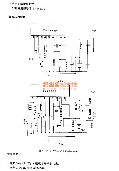
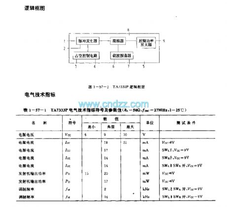
The TA7333P is designed as the wireless remote control launch circuit that can be used in the electronic toy application. The internal circuit is composed of the pulse generator, the mixer, RF power amplifier, duty ratio control circuit and the carrier frequency oscillator.
Features
It has little external components.The operating voltage range is wide (Vcc=6-10V).It is in the single-row 9-pin plastic package.The matching model is TA7657P.
Function description:
The switches SWL and SWR form the four kinds of control states.The capacitors C1 and R1 control the modulation frequency.
(View)
View full Circuit Diagram | Comments | Reading(1585)
CRYSTAL_OVEN_1
Published:2009/7/21 21:25:00 Author:Jessie
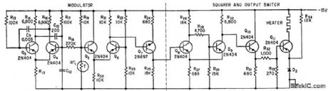
Thermistor RT1 senses temperature of crystal oscillator cavity and modifies output of asymmetric free running mvbr Q3-Q4 whose output is integrated by C12. Thermistor is followed by modulator, amplifier Q7, and four-transistor switch that applies power at fxed repetition frequency but with on time per cycle controlled by thermistor.-M. Lysobey, Microminiature Crystal Oscillator Using Wafer Modules, Electronics, 35:15, p 60-61.
(View)
View full Circuit Diagram | Comments | Reading(1025)
| Pages:934/2234 At 20921922923924925926927928929930931932933934935936937938939940Under 20 |
Circuit Categories
power supply circuit
Amplifier Circuit
Basic Circuit
LED and Light Circuit
Sensor Circuit
Signal Processing
Electrical Equipment Circuit
Control Circuit
Remote Control Circuit
A/D-D/A Converter Circuit
Audio Circuit
Measuring and Test Circuit
Communication Circuit
Computer-Related Circuit
555 Circuit
Automotive Circuit
Repairing Circuit