Communication Circuit
LOW_FREQUENCY_TRANSMITTER
Published:2009/7/8 22:04:00 Author:May | From:SeekIC

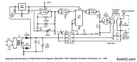
The crystal oscillator, which uses two sections of IC1, a 4001 quad 2-input NOR gate, is a standard and reliable design. The oscillator's 1.85-MHz, square-wave output feeds IC2, a 4017 divide-by-10 counter. The count enable and reset terminals, pins 13 and 15, are normally held high by resistor R3, and the counter is activated by bringing those pins low by closing telegraph key S1-an arrangement that guarantees that the final state of IC2 pin 12 is always high. The high on IC2 pin 12 is inverted by a third section of the 4001, IC1c, to prevent dc current flow through power amplifier Q1 during key-up periods.
Reprinted Url Of This Article:
http://www.seekic.com/circuit_diagram/Communication_Circuit/LOW_FREQUENCY_TRANSMITTER.html
Print this Page | Comments | Reading(3)

Article Categories
power supply circuit
Amplifier Circuit
Basic Circuit
LED and Light Circuit
Sensor Circuit
Signal Processing
Electrical Equipment Circuit
Control Circuit
Remote Control Circuit
A/D-D/A Converter Circuit
Audio Circuit
Measuring and Test Circuit
Communication Circuit
Computer-Related Circuit
555 Circuit
Automotive Circuit
Repairing Circuit
Code: