
Circuit Diagram
Index 930
LOW_NOISE_DC_REGULATOR_FOR_OSCILLATOR_CIRCUITS
Published:2009/7/21 3:01:00 Author:Jessie

This regulator uses FET devices for low-noise dc output needed for use with variable-frequency free-running oscillators. (View)
View full Circuit Diagram | Comments | Reading(814)
KA2182/KA2183 (TV) infrared remote control receiving preamplifier circuit
Published:2011/7/27 19:20:00 Author:TaoXi | Keyword: TV, infrared, remote control, receiving, preamplifier circuit
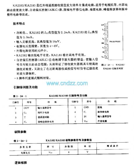
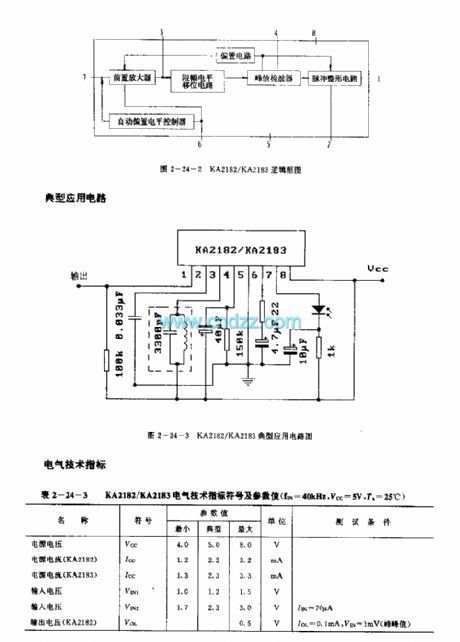
The KA2182/KA2183 is designed as the infrared remote control receiving preamplifier silicon single chip circuit that can be used in the TV application. The internal circuit is composed of the preamplifier, the Automatic bias controller (ABLC), amplitude limiting level shift circuit,biasing circuit, peak value detector and the pulse plastic circuit.
Features
Low power consumption. The Icc typical value of the KA2182 is 2.2mA, the Icc typical value of the KA2183 is 2.3mA.High input sensitivity, the typical value is 50uV.Wide input voltage range, the value is 4-8V.Little external components.The output low level of the KA2182 is effective, The output high level of the KA2183 is effective.
(View)
View full Circuit Diagram | Comments | Reading(592)
KA2184 (TV and video recoder) remote control receiving preamplifier circuit
Published:2011/7/27 20:21:00 Author:TaoXi | Keyword: TV, video recoder, remote control, receiving, preamplifier circuit
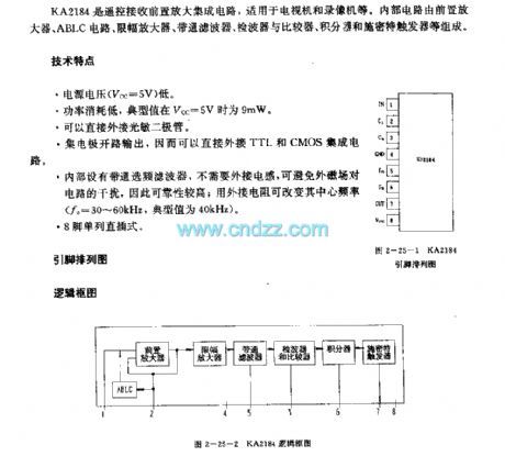
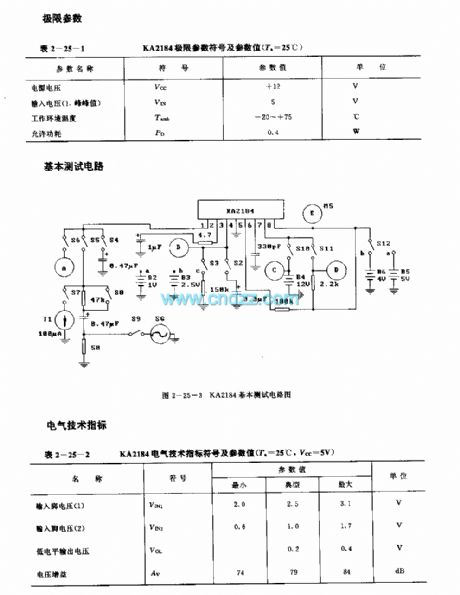
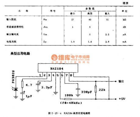
The KA2184 is designed as one kind of remote control receiving preamplifier circuit that can be used in the TV and video recoder applications. The internal circuit is composed of the preamplifier, the ABLC circuit, the amplitude limiting circuit, the bandpass filter, the wave detector, the comparator, the integrator, the Schmitt trigger.
Features
The power voltage is low (Vcc=5V).The power consumption is low, the typical value is 9mW when the typical value is 5V.It can be connected with the photosensitive diode directly.The collector is in the open-circuit output state, so you can connected it with the TTL and CMOS directly.It has the bandpass filter frequency selection filter.
(View)
View full Circuit Diagram | Comments | Reading(829)
LA7224 (TV and video recorder) infrared remote control receiving preamplifier circuit
Published:2011/7/27 20:35:00 Author:TaoXi | Keyword: TV, video recorder, infrared, remote control, receiving, preamplifier circuit
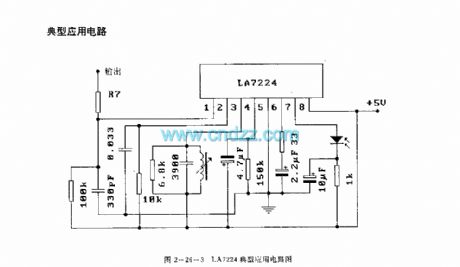
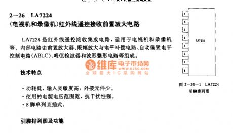
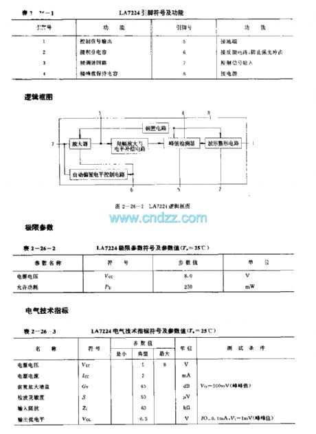
The LA7224 is designed as the infrared remote control receiving preamplifier circuit that can be used in the TV and video recorder applications. The internal circuit is composed of the preamplifier circuit, the amplitude limiting amplifier and level compensation circuit, the automatic bias level control circuit (ABLC), the peak value wave detector and the waveform plastic circuit.
Features
Low power consumption, high input sensitivity, little external components.The power voltage range is wide, the anti-interference performance is good.8-pin single DIP package.
(View)
View full Circuit Diagram | Comments | Reading(1329)
TUNABLE_AUDIO_FILTER
Published:2009/7/8 22:54:00 Author:May

This circuit uses a Wien Bridge and variable negative feedback. R7 controls the gain and R8A and R8B controls the tuned frequency. (View)
View full Circuit Diagram | Comments | Reading(0)
DOOR_BUZZER
Published:2009/7/8 22:53:00 Author:May

An LF357 functions as a swept-tone oscillator, driving Q1 and SPKRl. A 9-Vdc supply is required. (View)
View full Circuit Diagram | Comments | Reading(770)
KA2181 (TV and video recoder) infrared remote control receiving preamplifier circuit
Published:2011/7/27 21:02:00 Author:TaoXi | Keyword: TV, video recoder, infrared, remote control, receiving, preamplifier circuit
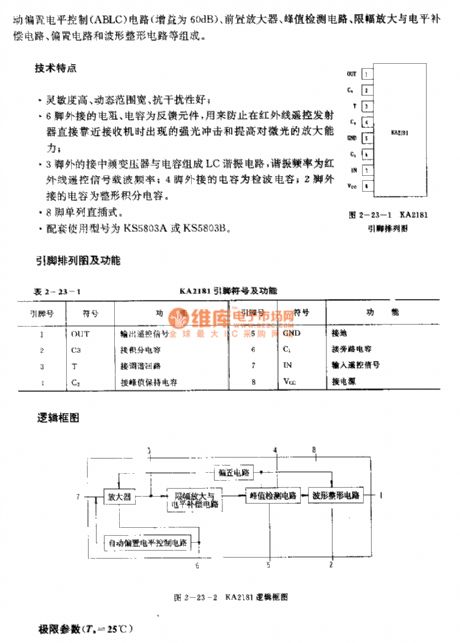
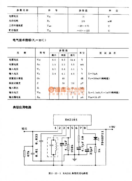
The KA2181 is designed as the infrared remote control receiving preamplifier circuit that can be used in the TV and video recoder applications. The internal circuit is composed of the automatic bias level control circuit (ABLC), the preamplifier circuit, the peak value detector, the amplitude limiting amplifier and level compensation circuit, the biasing circuit and the waveform plastic circuit.
Features
High sensitivity, wide dynamic range, good anti-interference performance.The external resistances and capacitances of pin-6 are the feedback components.The LC resonant circuit is composed of the medium frequency transformer and the capacitance.The 8-pin single row DIP package.The matching models are KS5803A or the KS5803B.
(View)
View full Circuit Diagram | Comments | Reading(680)
DC_LATCHING_RELAY
Published:2009/7/8 22:53:00 Author:May

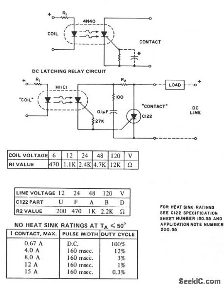
The H11C supplies the dc latching relay function and reverse polarity blocking, for currents up to 300 mA, depending on ambient temperature. For dc use, the gate cathode resistor can be supplemented by a capacitor to minimize transient and dV/dt sensitivity. For pulsating dc operation, the capacitor value must be designated to either retrigger the SCR at the application of the next pulse or prevent retriggering at the next power pulse. If not, random or undesired operation might occur. For higher current contacts, the H11C can be used to trigger an SCR capable of handling the current, as illustrated.
(View)
View full Circuit Diagram | Comments | Reading(1160)
LJA7225 (Video recorder and TV set) infrared remote control receiving preamplifier circuit
Published:2011/7/27 21:46:00 Author:TaoXi | Keyword: Video recorder, TV set, infrared, remote control, receiving, preamplifier circuit
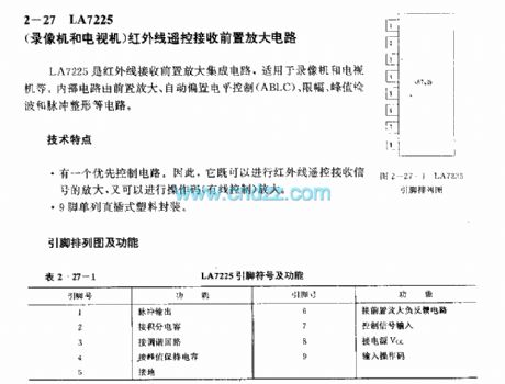
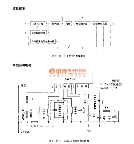
The LJA7225 is designed as the infrared remote control receiving preamplifier circuit that can be used in the video recorder and TV set applications. The internal circuit is composed of the preamplifier circuit, the automatic bias level control circuit (ABLC), the amplitude limiting circuit, the peak value wave detection circuit, the waveform plastic circuit.
Features
It has the priority control circuit, so it can amplify the infrared remote control receiving signal and the operation code.It is in the 9-pin single row DIP plastic package.
(View)
View full Circuit Diagram | Comments | Reading(620)
ELECTRONIC_DOOR_BUZZER
Published:2009/7/8 22:52:00 Author:May

When S1 is depressed, an initial positive voltage is placed on C2 and the noninverting terminal of U1.The circuit oscillates at a low frequency. As C2 charges up through R3, a rapid increase in frequency of oscillation results, producing (at SPKR1) a rapidly rising pitched sound. This sound is easily recognized over ambient noise. (View)
View full Circuit Diagram | Comments | Reading(1584)
ZERO_VOLTAGE_SWITCHING,SOLID_STATE_RELAY_WITH_ANTIPARALLEL_SCR_OUTPUT
Published:2009/7/8 22:51:00 Author:May
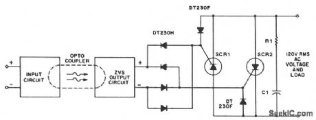
A higher line voltage can be used if the diode, varistor, ZVS, and power thyristor settings are at compatible levels. For applications beyond triac current ratings, antiparallel SCRs might be triggered by the ZVS network. (View)
View full Circuit Diagram | Comments | Reading(3320)
KAA3009/SAA3049 infrared remote control decoder circuit
Published:2011/7/27 21:17:00 Author:TaoXi | Keyword: infrared, remote control, decoder circuit
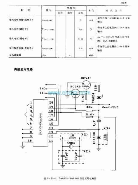
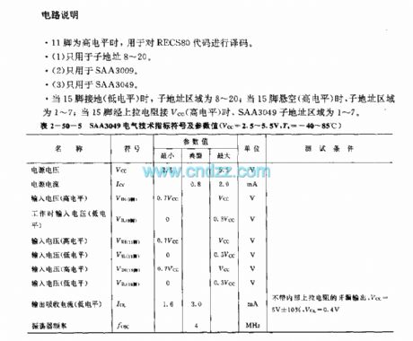
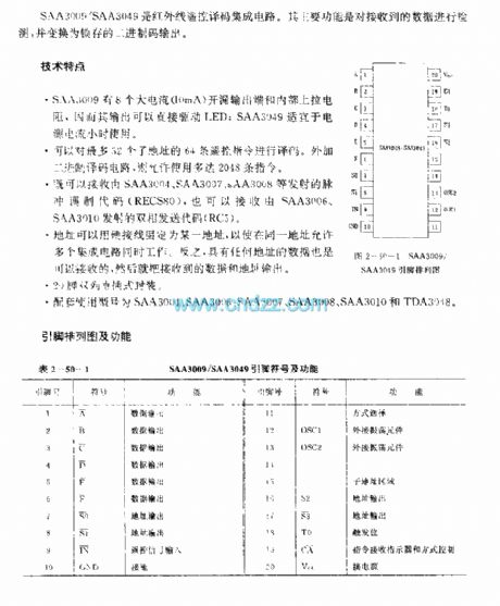
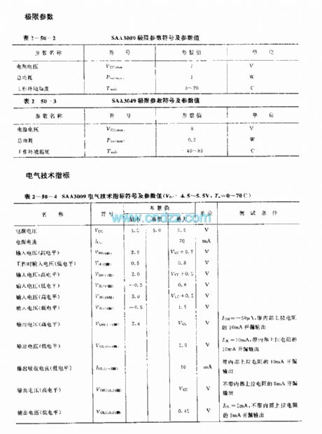
The SAA3009/SAA3049 is designed as the infrared remote control decoder circuit. The main function of this device is to detect the received data and change the data into the binary code.
Features
The SAA3009 has eight large current (10mA) open-drain output port and the internal pull-up resistance, because the output of it can drive the LED directly, the SAA3049 can be used in the small power current condition.
It can decode the 64 remote control instructions of 52 addresses.
It can receive the pulse modulation codes of SAA3004, SAA3007 and SAA3008, also it can receive the diphase sending codes of SAA3006, SAA3010.
(View)
View full Circuit Diagram | Comments | Reading(2024)
_OPTICAL_TTL_COUPLER
Published:2009/7/8 22:49:00 Author:May
For higher speed applications, up to 1-MHz NRZ, the Schmitt-trigger output H11L series optoisolator provides many features. The 1.6-mA drive current allows fan-in circuitry to drive the IRED, while the 5-V, 270-Ω sink capability and 100-ns transition times of the output add to the logic coupling flexibility. (View)
View full Circuit Diagram | Comments | Reading(836)
HT-7706 (Lighting) light control circuit
Published:2011/7/27 21:32:00 Author:TaoXi | Keyword: Lighting, light control
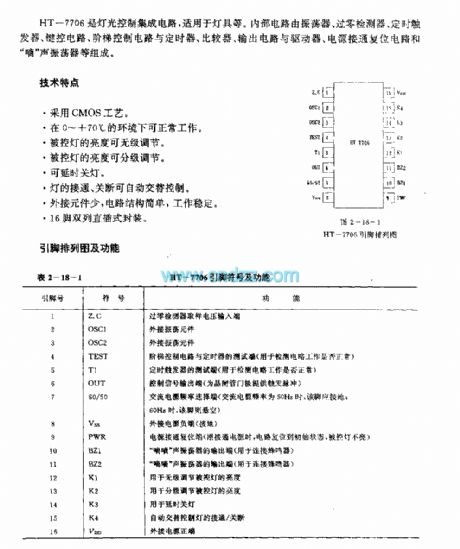
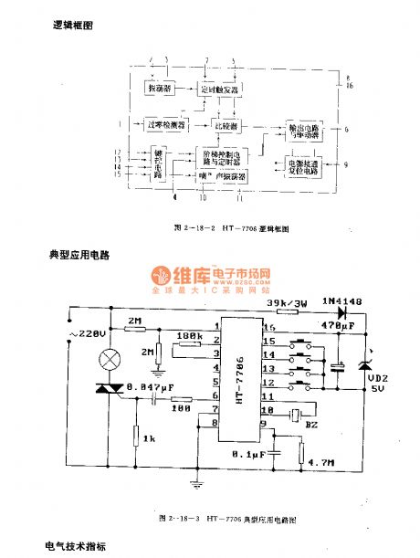
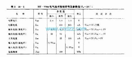
The HT-7706 is designed as the light control circuit that can be used in the lighting application. The internal circuit is composed of the oscillator, the zero crossing detector, the timing trigger, the button control circuit, the stage control circuit, the timer, the comparator, the output circuit, the driver, the power connection reset circuit and the di sound oscillator.
Features
The CMOS technology.It can operate normally in the environment of 0 to +70℃.The brightness of the controlled light is stepless adjusting mode.The brightness of the controlled light has two stages.The delay turn-off function.The automatic alternate turn-on and turn-off.
(View)
View full Circuit Diagram | Comments | Reading(647)
NEON_LAMP_OSCILLATOR
Published:2009/7/21 3:02:00 Author:Jessie
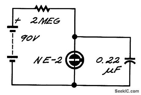
The neon lamp has negative dynamic resistance-the voltage across it falls while conduction is increasing. As a result, it flashes on and off.The frequency depends on the time constant RC and the supply voltage, as well as lamp characteristics. (View)
View full Circuit Diagram | Comments | Reading(1303)
34_GHz_MICROWAVE_PREAMP
Published:2009/7/8 22:48:00 Author:May
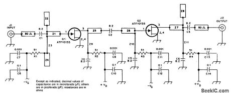
At 3.45 GHz, this 2-stage preamp has a gain of 23 dB (typical) and less than 1dB NF. (View)
View full Circuit Diagram | Comments | Reading(476)
LINE_CURRENT_DETECTOR
Published:2009/7/8 22:47:00 Author:May
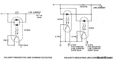
Detection of line-current flow and indicating the flow to an electrically remote point is required in line status monitoring at a variety of points in the telephone system and auxiliary systems. The line should be minimally unbalanced or loaded by the monitor circuit, and relatively high levels of 60-Hz induced voltages must be ignored. The H11AA1 allows line currents of either polarity to be sensed without discrimination and will ignore noise up to approximately 2.5 mA. In applications where greater noise immunity or polarity-sensitive line-current detection is required, the H11A10 threshold coupler can be used. This phototransistor coupler is specified to provide a minimum 10% current transfer ratio at a defined input current, while leaking less than 50 μA at half that input current over the full -55℃ to + 100℃ temperature range.The input current range, at which the coupler is on, is programmable by a single resistor from 5 to 10 mA. (View)
View full Circuit Diagram | Comments | Reading(1262)
Precision_amolifier_with_closed_loop_voltage_gain_of_1000_using_an_ECG925
Published:2009/7/21 3:03:00 Author:Jessie
Precision amolifier with closed loop voltage gain of 1000 using an ECG925. Typical supplyvoltage is ±15 volts, but it can be powered with 6 supplies from ±3 volts to ±22 volts (courtesy GTE Sylvanta Incorporated). (View)
View full Circuit Diagram | Comments | Reading(681)
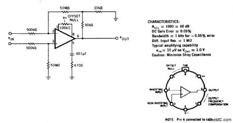
HIGH_GAN_FOR_WEAK_SIGNALS
Published:2009/7/8 22:46:00 Author:May

NationaI LM121 differential amplifier is operated openloop as input stage for input signals up to ±10 mV. Input voltage is converted to differential output current for driving opamp acting as current-to-voltage converter with single-ended output. R4 is adjusted to set gain at 1000. Null pot R3 serves for offset adjustment. - Linear Applications, Vol, 2, National Semiconductor, Santa Clara, CA, 1976, AN-79, p 7-8. (View)
View full Circuit Diagram | Comments | Reading(689)
OPTICAL_CMOS_COUPLER
Published:2009/7/8 22:46:00 Author:May


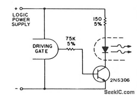
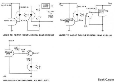
required current to the IRED if CMOS is to drivethe optocoupler.As in the case of the low output TTL families,the H74A output can drive a multiplicity of CMOS gate inputs or a standard TTL input given the proper bias of the IRED. A onelogic stage drives the IRED on. This circuit will provide worst-case drive criteria to the IRED for logic supply voltages from 3 to 10 V, although lower power dissipation can be obtained by using higher value resistors for high supply voltages. If this is desired, the worst-case drive must be supplied to the IRED with minimum supply voltage, minimum temperature and maximum resistor tolerances, gate saturation resistance, and transistor saturation voltages applied. For the H74 devices, minimum IRED current at worst-case conditions, zero logic state output of the driving gate, is 6.5 mA and the H11L1 is 1.6 mA. (View)
View full Circuit Diagram | Comments | Reading(683)
| Pages:930/2234 At 20921922923924925926927928929930931932933934935936937938939940Under 20 |
Circuit Categories
power supply circuit
Amplifier Circuit
Basic Circuit
LED and Light Circuit
Sensor Circuit
Signal Processing
Electrical Equipment Circuit
Control Circuit
Remote Control Circuit
A/D-D/A Converter Circuit
Audio Circuit
Measuring and Test Circuit
Communication Circuit
Computer-Related Circuit
555 Circuit
Automotive Circuit
Repairing Circuit