Control Circuit
_PWM_MOTOR_CONTROLLER
Published:2009/7/8 5:14:00 Author:May | From:SeekIC

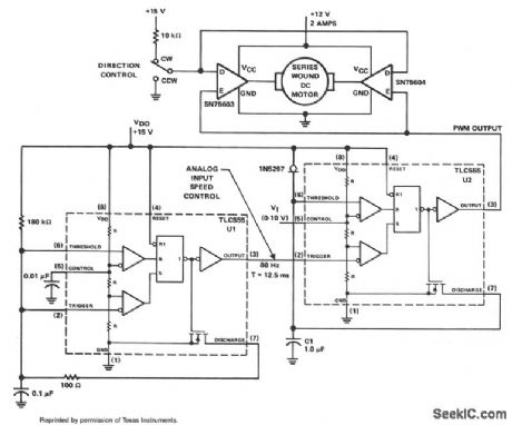
The PWM controller uses complementary half-H peripheral drivers SN75603 and SN75604, with totem-pole outputs rated at 40 V and 2.0 A. These drivers effectively place the motor in a full-bridge configuration, which has the ability to provide bidirectional control.
Timer U1 operates in the astable mode at a frequency of 80 Hz. The 100-Ω discharge resistor results in an 8-μs trigger pulse which is coupled to the trigger input of timer U2. Timer U2 serves as the PWM generator. Capacitor C1 is charged linearly with a constant current of 1 mA from the 1N5297, which is an FET current-regulator diode.
Motor speed is controlled by feeding a dc voltage of 0 to 10 V to control input pin 5 of U2. As the control voltage increases, the width of the output pulse pin 3 also increases. These pulses control the on/off time of the two motor drivers. The trigger pulse width of timer U1 limits the minimum possible duty cycle from U2.
Reprinted Url Of This Article:
http://www.seekic.com/circuit_diagram/Control_Circuit/_PWM_MOTOR_CONTROLLER.html
Print this Page | Comments | Reading(3)

Article Categories
power supply circuit
Amplifier Circuit
Basic Circuit
LED and Light Circuit
Sensor Circuit
Signal Processing
Electrical Equipment Circuit
Control Circuit
Remote Control Circuit
A/D-D/A Converter Circuit
Audio Circuit
Measuring and Test Circuit
Communication Circuit
Computer-Related Circuit
555 Circuit
Automotive Circuit
Repairing Circuit
Code: