Basic Circuit
AUTOMATIC_CALIBRATOR
Published:2009/7/8 22:36:00 Author:May | From:SeekIC

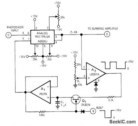
Automatic scaling circuit permits frequent and fast recalibration for precision optical measurements, to compensate for variations in light intensity due to thermal cycling of lamp filament, dirty optics, and gain variations between photodetectors and between amplifiers. With reset pulse at point B, comparator A2 compares output of multiplier to preset reference voltage on R1. If A2 input voltage is greater than reference applied to pin 3 by R2, output switches to zero and remains there until C1 has discharged enough to lower output of A1 and output of multiplier below reference on pin 3. If input at pin 2 ofA2 is less than reference on pin 3,A2 will switch to 15 V and output of multiplier will be adjusted upward until voltage on pin 2 of A2 again exceeds that on pin 3. Output of A2 is thus continually switching between 15 V and 0 V during reset or scaling. After reset pulse is removed, scale factor K is maintained constant by multiplier during measuring.-R. E. Keil, Automatic Scaling Circuit for Optical Measurements, EDN/EEE Magazine, Nov. 15, 1971, p 49-50.
Reprinted Url Of This Article:
http://www.seekic.com/circuit_diagram/Basic_Circuit/AUTOMATIC_CALIBRATOR.html
Print this Page | Comments | Reading(3)

Article Categories
power supply circuit
Amplifier Circuit
Basic Circuit
LED and Light Circuit
Sensor Circuit
Signal Processing
Electrical Equipment Circuit
Control Circuit
Remote Control Circuit
A/D-D/A Converter Circuit
Audio Circuit
Measuring and Test Circuit
Communication Circuit
Computer-Related Circuit
555 Circuit
Automotive Circuit
Repairing Circuit
Code: