Communication Circuit
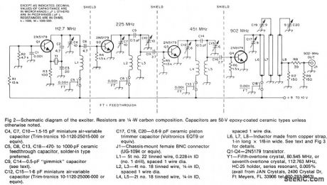
902_MHz_CW_TRANSMITTER
Published:2009/7/8 22:36:00 Author:May | From:SeekIC

The oscillator, Q1, is a standard overtone circuit. A fifth-overtone crystal, 80.545 MHz, is operated on the seventh overtone, 112.763 MHz. C6 couples the output of the oscillator to Q2, which operates as a doubler to 225.5 MHz. A double-tuned circuit using C7, L2, L3, C10 is used in the collector of Q2 to reduce the level of the 112-MHz oscillator signal. The output of Q2 is capacitively coupled at C11 to the base of Q3. The double-tuned circuit in the collector of Q3 with C12, L4, L5, C15, is tuned to 451 MHz. A small capacitance, 2.7 pF, couples the 451-MHz signal to the base of another 2N5179, Q4, which doubles the signal to 902 MHz. The output of the 902-MHz doubler has a triple-tuned circuit using C17, L6, C19, L7, C20, L8 in its collector.
Reprinted Url Of This Article:
http://www.seekic.com/circuit_diagram/Communication_Circuit/902_MHz_CW_TRANSMITTER.html
Print this Page | Comments | Reading(3)

Article Categories
power supply circuit
Amplifier Circuit
Basic Circuit
LED and Light Circuit
Sensor Circuit
Signal Processing
Electrical Equipment Circuit
Control Circuit
Remote Control Circuit
A/D-D/A Converter Circuit
Audio Circuit
Measuring and Test Circuit
Communication Circuit
Computer-Related Circuit
555 Circuit
Automotive Circuit
Repairing Circuit
Code: