© 2008-2012 SeekIC.com Corp.All Rights Reserved.
Basic Circuit
WIRELESS_FM_MICROPHONE_1
Published:2009/7/8 22:31:00 Author:May | From:SeekIC

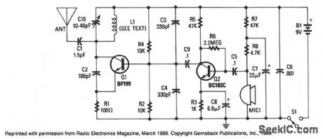
Adjustable capacitor C10, and coil L1 form a tank circuit that, in combination with Q1, C2, and R1, oscillates at a frequency on the FM band. The center frequency is set by adjusting C10. An electret microphone, M1, picks up an audio signal that is amplified by transistor Q2. The audio signal is coupled via C9 to Q1, which frequency modulates the tank circuit. The signal is then radiated from the antenna. The circuit can operate from 9-12 Vdc.
Reprinted Url Of This Article:
http://www.seekic.com/circuit_diagram/Basic_Circuit/WIRELESS_FM_MICROPHONE_1.html
Print this Page | Comments | Reading(3)

Article Categories
power supply circuit
Amplifier Circuit
Basic Circuit
LED and Light Circuit
Sensor Circuit
Signal Processing
Electrical Equipment Circuit
Control Circuit
Remote Control Circuit
A/D-D/A Converter Circuit
Audio Circuit
Measuring and Test Circuit
Communication Circuit
Computer-Related Circuit
555 Circuit
Automotive Circuit
Repairing Circuit
New published articles
Response in 12 hours
About SeekIC | Services | Payment | Advertisements service | Contact Us | Links

Code: