
Circuit Diagram
Index 709
ELECTROSTATIC_SQUARER
Published:2009/7/16 4:16:00 Author:Jessie

Used to obtain integrated reading of reflected sound patterns when measuring acoustic characteristics of auditoriums. Electrostatic squarer in-corporates frequency-determining elements of two transitron negative-resistance oscillators (3.3 and 3.8 Mc). Amplified outputs are mixed to obtain 500-kc difference signal which in turn is mixed with 500-kc crystal oscillator output to give from0 to 35 kc for feeding to counter.-J. P. A. Lochner and P. Meffert, Electrostatic Squarer for Acoustic Measurements, Electronics, 33:35, p 66-68. (View)
View full Circuit Diagram | Comments | Reading(726)
9_MHz_TUNED_OUTPUT
Published:2009/7/16 4:15:00 Author:Jessie
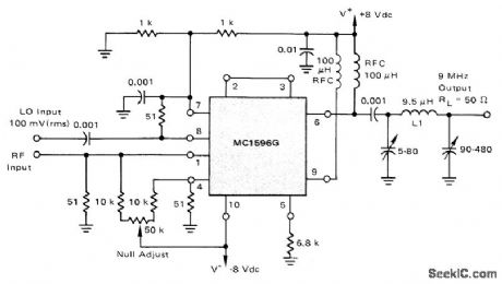
Motorola MC1596G balanced modulator connected as double-balanced mixer has 3-dB bandwidth of 450 kHz at output. Local oscillator signal LO is injected at upper input port and modulated signal of about 15 VRMS maximum at lower input port. Conversion gain is 13 dB for 30-MHz input and 39-MHz LO.-R. Hejhall, MC1596 Balanced Modulator, Motorola, Phoenix, AZ, 1975, AN-531, p7.
(View)
View full Circuit Diagram | Comments | Reading(864)
TIME_DELAYED_SCHMITT_AS_SENSOR
Published:2009/7/13 4:00:00 Author:May
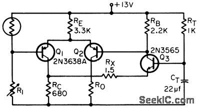
Provides delay in sensor control until industrial process and system are started up and in normal operating mode. Delay is obtained with R-C network in additional transistor stage Q3.Photocell and R1 are interchangeable depending on polarity of control required from output.-L. T. Medveson, Time-Delayed Schmitt Sensor, EEE,14:7, p104. (View)
View full Circuit Diagram | Comments | Reading(1069)
LC_SELF_CALIBRATING_METER
Published:2009/7/16 4:15:00 Author:Jessie


This circuit uses a microcontroller and a LED display,IC1 is an oscillator in which the unknown component is placed for measurement,and IC2 is a PIC16C61 microcontroller that calculates the unknown value and drives the LCD The microcontroller must be programmed;the program is given in listing 1. (View)
View full Circuit Diagram | Comments | Reading(1045)
60_LED_SEQUENTIAL_DRIVER
Published:2009/7/13 4:00:00 Author:May

This circuit is useful as the minute hand for an LED clock or a general-purpose sequential driver. (View)
View full Circuit Diagram | Comments | Reading(1342)
NULL_DETECTOR
Published:2009/7/13 3:59:00 Author:May

This null detector is based on the Linear Technology LTC1050 amplifier. Chopper stabilized, it provides performance that is almost driftfree. The low-frequency gain is guaranteed to be over 130 dB, so only one amplifier stage is needed. Input bias and offset currents are in the picoampere region, and, finally, the sample-and-hold capacitors have been incorporated within the amplifier, further simplifying the null detector's design. The circuit must be battery-powered, but no cells give reasonable positive and negative supply values. The answer lies in the TLE2426 rail splitter ground IC. Using this special divider/buffer, a standard 9-V battery will provide 4.5-V supplies-perfect for the CMOS chopper amplifier. The input of this detector is limited to a maximum of 100 mV. The most sensitive range is 10 μV, full scale. This allows the detector to resolve 1-μV differences with no difficulty The input impedance will be 200 kΩ for normal inrange signals,falling to a minimm of 40 kΩ under overload conditions The limiting factor is the voltage rating of the first input-filter capacitor,which runs at about one half of the input voltageunder overload conditions. (View)
View full Circuit Diagram | Comments | Reading(0)
SOLION_TIME_BASE
Published:2009/7/16 4:15:00 Author:Jessie

Electrical readout integrator consisting of solion liquid diode provides readout current that increases linearly with lime for constant current input, permitting use of input to axes of X-Y recorder.-R. N. Lane and D. B. Cameron, Current Integration with Solion Liquid Diodes, Electronics, 32:9, p 53-55. (View)
View full Circuit Diagram | Comments | Reading(645)
REGULATOR_FOR_PORIABLE_CRO
Published:2009/7/16 4:15:00 Author:Jessie

Maintains constant 10-v output from 12-v nickel-cadmium battery, from external d-c voltages up to 35 v, or from 117-v a-c line. Includes battery-charging circuit, in which thermistor R1 senses rise in battery temperature and turns off charger when battery is fully charged.-O. Svehaug and J. R. Kobbe, Battery-Operated Transistor Oscilloscope, Electronics, 33:12, p 80-83. (View)
View full Circuit Diagram | Comments | Reading(825)
2_min_RAMP
Published:2009/7/13 3:58:00 Author:May
Used in multiple timer for development of photographic paper, in which six independent timers are started in sequence as each sheet of exposed paper is placed in developer. C1 is 1 μF and R1 is 11 megohms for 2-min timer having accuracy within 5 s. Article gives all other circuits required and suggests modifications to meet other needs. Output B drives meter and trigger circuit for audible alarm.Timer is started by input switch connected to A.-R. G. Wicker, Photographic Development Timer, Wireless World, April 1974, p 87-90. (View)
View full Circuit Diagram | Comments | Reading(728)
SIMPLE_ANTENNA_TUNER
Published:2009/7/13 3:57:00 Author:May

This simple tuner can properly match anything from a bedspring to a long-wire antenna. Be sure to use a voltage -transmitting-type unit for C1 if more than 5 W of output power is to be used. (View)
View full Circuit Diagram | Comments | Reading(21938)
GYRO_TORQUING_SWITCH
Published:2009/7/13 3:57:00 Author:May

Flip-flop Q1-Q2 controls Q3 driving switching transistor Q4.Trigger signals from telemetry receiver programmer control state of flip-flop. Can pass 400-cps square wave with 10-V peak.-J. H.Porter, Miniaturized Autopilot System for Missiles, Electronics, 33:43, p60-64. (View)
View full Circuit Diagram | Comments | Reading(827)
450_MC_R_F_AMPLIFIER
Published:2009/7/13 3:57:00 Author:May
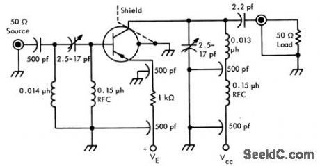
Gives averago Power gain of 8.6 db, bandwith of 48 Mc, and noise figure of 6 db Uses linear active network, designed with Linvill chart. Lead inductance was minimized by removing most of the Teflon from TO-18 socket so only thin disk, approximately chassis thickness, remains-Texas Instruments Inc., Solid-State Communcations, McGrow-Hill, NY.,1966, p 97.
(View)
View full Circuit Diagram | Comments | Reading(747)
TOROIDAL_TRANSFORMER
Published:2009/7/13 3:56:00 Author:May

The several types of impedance matching transformers are∶1:1 baiun (A).4:1balun (B).9:1 unun (C).and 16:1 un-un (D) (View)
View full Circuit Diagram | Comments | Reading(2137)
GAIN_CONTROLLED_LOG_AMPLIFIER
Published:2009/7/13 3:56:00 Author:May

Based on fact that gain of common-emitter fet stage is almost inversely proportional to emitter resistance, and resistance of let operating below cutoff is linear function of grid voltage. Can be used as agc amplifer and as multiplier.-Y. J. Lubkin, Gain Controlled Log Ampliler, GEE, 10:9, p 91. (View)
View full Circuit Diagram | Comments | Reading(760)
450_MHz_PREAMP
Published:2009/7/16 4:14:00 Author:Jessie
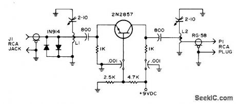
Provides up to 10-dB extra gain for older tube-type 450-MHz receivers. Gives significant improvement in receiver sensitivity and quieting. Use of trough-line inductors simplifies construction. 1N914 diodes in parallel at input jack protect transistor from burnout by nearby transmitter. L1 and L2 are made from 1/4-inch diameter copper tubing, 8.6 cm long. Article covers construction and operation.-C. Klinert, Easy Preamp for 450 MHz, 73 Magazine, May 1973, p 33 and 36-38. (View)
View full Circuit Diagram | Comments | Reading(1196)
SOLION_INTEGRATING_NOISE_METER
Published:2009/7/16 4:14:00 Author:Jessie

Audio amplifier for microphone feeds visual-read-out solion integrator through rectifying diode. Used to measure extent of exposure of per son to dangerously high levels of noise.-R. N. Lane and D. B. Cameron, Current Integration with Solion Liquid Diodes, Electronics, 32:9, p 53-55. (View)
View full Circuit Diagram | Comments | Reading(746)
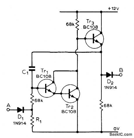
EXTRA_TRANSISTOR_STABILIZES_ONE_SHOT
Published:2009/7/16 4:13:00 Author:Jessie

Q1 isolates triggering circuit from timing elements R2-C2, making duration of output pulse independent of input pulse amplitude and reducing minimum triggering voltage from 0.25 V to 0.l V.-J. Kalisz, Isolating Transistor Improves One-Shot, Electronics, 38:25, p 76. (View)
View full Circuit Diagram | Comments | Reading(738)
MEASURING_INTEGRAL_OF_CURRENT_PULSES
Published:2009/7/16 4:13:00 Author:Jessie

Gives current integral of one or more pulses, for measuring quantity of electricity in coulombs, regardless of pulse shape and independently of ground connection or circuit potential. Commercial d-c electrometer may be used in place of operational amplifier. Range switch is at pickup.-J. F. Howell, How to Measure Coulombs in Irregular Pulses, Electronics, 35:32, p 72-73. (View)
View full Circuit Diagram | Comments | Reading(678)
THYRATRON_CONTROLS_CHARGER_RECTIFIER
Published:2009/7/16 4:13:00 Author:Jessie

Automatic regular turns charger off when battery voltage exceeds predetermined value, and turns charger on again automatically at any desired lower voltage from 5 to 7.5 v. Line voltage changes do not affect adjustment.-J, Markus and V. Zeluff, Handbook of Industrial Electronic Circuits, McGraw-Hill, N.Y., 1948, p 257. (View)
View full Circuit Diagram | Comments | Reading(820)
NOISE_IMMUNE_BISTABLE
Published:2009/7/16 4:11:00 Author:Jessie

C2 gives immunity to accidental triggering by noise, though with some reduction in switching speed. When C2 is 0.1 mfd, upper frequency limit is 400 cps, and is 100 cps for O.47 mfd. -R. W. Simister, Bistable Multivibrator Immune to Noise, Electronics, 39:6, p 97. (View)
View full Circuit Diagram | Comments | Reading(768)
| Pages:709/2234 At 20701702703704705706707708709710711712713714715716717718719720Under 20 |
Circuit Categories
power supply circuit
Amplifier Circuit
Basic Circuit
LED and Light Circuit
Sensor Circuit
Signal Processing
Electrical Equipment Circuit
Control Circuit
Remote Control Circuit
A/D-D/A Converter Circuit
Audio Circuit
Measuring and Test Circuit
Communication Circuit
Computer-Related Circuit
555 Circuit
Automotive Circuit
Repairing Circuit