
Circuit Diagram
Index 701
SIMPLE_SWR_BRIDGE
Published:2009/7/16 3:35:00 Author:Jessie

This circuit can be used to measure SWR. It uses a coupler made from a 6.5-inch piece of RG-58A/U coax. First remove the outer plastic jacket, then open up the braid a little bit. Next, thread two lengths of #22 tinned bus wire into Teflon spaghetti. Then thread the insulated wires inside the braid, trying to keep them on opposite sides of the center conductor. Be careful to keep the leads to the 1N67A diodes and the 150-Ω resistors very short. If you can't find 1N67A diodes, use 1N34. The RG-58A/U braid should, of course, be grounded at both ends. If the device is carefully constructed, the result should be a perfectly balanced VSWR meter. It should need no adjustment. (View)
View full Circuit Diagram | Comments | Reading(5275)
RCTL_NAND_NOR_GATE
Published:2009/7/16 3:34:00 Author:Jessie

Resistors and capacitors in base circuits permit higher fan-out and give logic swing of 2v for high noise rejection in integrated-circuit logic.-A. E, Skoures, Choosing Logic for Microelectronics, Electronics, 36:40, p 23-26. (View)
View full Circuit Diagram | Comments | Reading(586)
1296_MHz_TO_285_MHz
Published:2009/7/16 3:34:00 Author:Jessie

Uses UHF transistors in active mixer and in final stage of injection chain, for lower noise figure and useful conversion gain. Doubler and tripler stages are individually shielded. -L. Crutcher, An Active-Mixer Converter for 1296 MHz, QST, Aug. 1974, p 11-14. (View)
View full Circuit Diagram | Comments | Reading(1973)
1_WATT_AUDIO_AMP
Published:2009/7/16 3:34:00 Author:Jessie

Negative d-c and ac feedback is applied to one side of differential input stage and signal to other side. With balanced power supplies, d-c output is at ground, permitting direct drive of speaker without lage d-e decoupling capacitor in MC1524 integrated circuit.-R. Hirschfeld, IC's Improve Differential Amplifiers-and Vice Versa, Electronics, 38:16, p 75-79. (View)
View full Circuit Diagram | Comments | Reading(816)
CHRONOMETER_COUNTER
Published:2009/7/16 3:33:00 Author:Jessie

The chronometer has four 7-segment displays, which can show a time lapse of 000.0 s to 999.9 s with a resolution of 0.1 s or a count from 0000 up to 9999. The chronometer is based on the type 74C925 counter IC with integrated display driver from National Semiconductor. The device draws a current of about 40 mA from a +5-V supply. On power-up, the counter is set to 0000 by network R14-C4 or by S1. The IC can derive a clock from two different sources: the internal oscillator or an external one via the COUNT input. The oscillator is formed by IC2c and IC2d and is enabled via the timer input. The enabling is effected manually by S3 or by inputting a given level, high or low, depending on the position of 53, into CHRON. The timer and counter inputs are identical, but are separated electrically from one another and from the signal source by optoisolators. This allows input potentials of up to 25 VP-P to be applied to either of them. As with the timer input, the level at the COUNT input can be either high or low and is selected by S4. The position of S2b determines whether the time or count function is active. Switch section S2a inserts the decimal point between the third and fourth display digits when the timer is selected. Whereas a simple level is needed to start the oscillator, the signal at the COUNT input needs more if the module is to work error-free. The signal must have steep edges; it must be free of interference; at low level, it must be well below 1V; and at high level, it must well above 2V. Moreover, if a switch is used at the COUNT input, it must be debounced adequately. (View)
View full Circuit Diagram | Comments | Reading(5088)
SENSE_AMPLIFIER
Published:2009/7/16 3:33:00 Author:Jessie

General-purpose amplifier can be used with most coincident-current memories without redesign. Has adjustable threshold, good noise rejection, and drives any standard logic gate with positive or negative output. Bandwidth is 10 Mc. Drift is only 22 microvolts per ℃. Circuit is differential amplifier whose inputs are connected to opposite ends of sense winding. Input accepts both polarities, but output is always same polarity. For negative output pulse, connect F to G; for positive output, connect E to G.-B. Johnson, Sense Amplifier Fis Any Memory, Electronics, 39:18, p 9-94. (View)
View full Circuit Diagram | Comments | Reading(0)
SINGLE_CRYSTAL_FOR_46_TO_420_MHz
Published:2009/7/16 3:33:00 Author:Jessie

Covers all VHF amateur bands by using mixer-generated harmonics of 66-MHz crystal oscillator frequency for mixing action. IF can be tuned with any communication receiver. Fundamental is used directly, third harmonic of 138 MHz serves for 2 meters, fifth of 230 MHz for 220-MHz band, and ninth of 414 MHz for 420-MHz band. Q1-Q3 are broadband RF preamp. Y1 is plated overtone crystal oscillating at 46 MHz in series-resonant mode. Q5 and Q6 form differential-amplifier oscillator, and Q4 is mixer driver. No tuning is required in converter, but external tuning is required to prevent device from working on all bands at once. All transistors are part of RCA CA3049T IC, for which pin numbers are circled. L1 is 72 inches of No. 30 enamel, doubled and twisted 1 turn per inch and wound on 1-meg-ohm 1/2-W resistor to form quarter-wave trans-mission line. -S. Smith, Four-Band VHF Receiving Converter, Ham Radio, Oct. 1976, p 64-66. (View)
View full Circuit Diagram | Comments | Reading(924)
WIDEBAND_ANALOG_AMPLIFIER
Published:2009/7/16 3:32:00 Author:Jessie
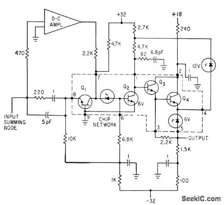
D-C input summing mode signals are amplified in low-drift d-c amplifier and reinserted info amplifier signal path at input to common-emitter stage. Response of d-c amplifier in parallel with common-base stage is complementary to high-frequency amplifier Q2-Q3-Q4, maintaining unit slope down to 1 kc, where gain is 100 db. Loop delay is less than 0.1 nsec. -F. D. Waldhauer, Latest Approach to Integrated Amplifier Design, Electronics, 36:22, p 24-27. (View)
View full Circuit Diagram | Comments | Reading(793)
ALL_CMOS_RECEIVER
Published:2009/7/16 3:32:00 Author:Jessie

Uses CD4007A IC, having complementary ρair of opamps and inverter, to provide all circuits for AM broadcast radio capable of driving headphones or 8-ohm loudspeaker, Selectivity is provided by single tuned circuit and can be improved by optimizing value of C1 to adjust antenna loading. Tune with C3, adjusting L1 if necessary to get stations at low end of band. - C. Green, Easy-to-Build CMOS Radio Receiver, Modern Electronics, Sept. 1978, p 4-41, 46, and 59. (View)
View full Circuit Diagram | Comments | Reading(867)
HARMONIC_MIXER
Published:2009/7/16 3:32:00 Author:Jessie

Two-transistor integrated circuit is used in nonlinear mode for converting 120 Mc to 10.7 Mc with conversion of 29.4 db, noise figure of 11 db, and sensitivity of -105 dbm. Bandwidth, including i-f stages that follow mixer, is about 500 kc.-J. E. Thompson, An Integrated Harmonic Mixer, Motorola Application Note AN-154, December, 1965. (View)
View full Circuit Diagram | Comments | Reading(1410)
LINEAR_IC_TESTER
Published:2009/7/16 3:30:00 Author:Jessie

Basic lab tester circuit displays transfer function, offset voltage, gain, linearity, and output voltage swing on single scope trace. High-gain null opera tional amplifier (such as Fairchild 709 IC) is used in feedback loop around linear integrated-circuit amplifier under test, to hold output of amplifier under test at zero by adjusting its d-c input voltage to equal the offset. Chopper on vertical scope inputs allows simultaneous display of offset voltage and transfer function, by switching in synchronism with horizontal sweep. Separate TO-5 socket is provided for each type of integrated circuit to be tested.-J. N. Giles, How to Measure Linear-IC Performance, EEE, 14:8, p 62-68 and 161. (View)
View full Circuit Diagram | Comments | Reading(1766)
1_PPS_GATE_OPENING_TIMER
Published:2009/7/16 3:30:00 Author:Jessie
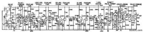
Produces pulses at 1-sec intervals to control gate of 400,000-rpm digital tachometer. Crystal oscillator produces 10-kc signal. Dekatrons are used to divide this to l-pps output.-J. K. Goodwin, Digital Tachometer Aids in Turbine Design, Electronics, 32:15, p 58-61. (View)
View full Circuit Diagram | Comments | Reading(620)
20_dB_PREAMP_FOR_160_METERS
Published:2009/7/16 3:30:00 Author:Jessie
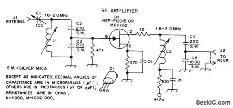
Provides badly needed extra gain when using Beverage or other inefficient low-noise receiving antennas. Gate of common-source JFET is tapped down on tuned circuit by capacitive divider C3-C4 to prevent self-oscillation. Mica compression trimmer C1 provides match to antenna. L1 and L2 are J. W. Miller 43-series slug-tuned coils; L1 has tuning range of 36-57 μH, and L2 has 24-40 μH range. For 160-meter band, L1 and L2 can be peaked at 1827 kHz to provide maximum gain in 1825-1830 kHz DX window.-D. DeMaw, Build This Quickie Preamp, QST, April 1977, p 43-44. (View)
View full Circuit Diagram | Comments | Reading(1494)
WWV_FET_CONVERTER
Published:2009/7/16 3:30:00 Author:Jessie

Receives WWV on 2.5, 5, 10, 15, ver operating and 20 MHz using modified transistor AM broadcast receiver operating straight-through for for 2.5.MJz reception and serving as IF amplifier for converter when tuned to higher WWV and WWVH frequencies. Only two crystals are needed because each allows reception of two WWV frequencies; thus, 10 and 20 MHz, are image frequencies when receiving 5 and 15 MHz. Loopstick antenna, of radio is replaced with small slug-tuned coil L6 to use 2.5-MHz image frequency when radio is tuned to 1590 kHz. Converter uses –dual-gate MOS FETs in RF stang Q1 and mixer Q2, with JFET Q3 as oscillator Antenna is short piece of wire. -H. Olson, Five-Frequency Receiver for WWV, Ham Radio, July 1976, P 36-38. (View)
View full Circuit Diagram | Comments | Reading(3106)
46_CPS_AMPLIFIER_WITH_8_CPS_BANDPASS
Published:2009/7/16 3:28:00 Author:Jessie
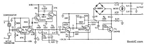
Uses differential input amplifier Q1-Q2 as part of four-stage direct-coupled front end of optically chopped radiometer. Parallel-T filter provides desired frequency characteristic and d-c path for negative feedback around direct-coupled amplifier.-F. Schwarz, Infrared Circuits in Tiros Satellites, Electronics, 34:38, p 43-45. (View)
View full Circuit Diagram | Comments | Reading(656)
20_METERS_TO_40_METERS
Published:2009/7/16 3:28:00 Author:Jessie

Used with 40-meter receiver for which circuit is also given. Converter output is in 40-meter band, for direct feed to input of receiver. L4 is 12 turns No. 26 enamel on Amidon FT37-61 toroid, L5 is 24 turns No. 26 enamel on Amidon 7-50-6 toroid, and T3 uses Amidon 7-50-6 toroid with 2 turns No. 26 enamel for primary and 21 turns for secondary. -D. DeMaw, The Mini-Miser's Dream Receiver, QST, Sept. 1976, p 20-23. (View)
View full Circuit Diagram | Comments | Reading(2229)
AUTO_IGNITION
Published:2009/7/16 3:28:00 Author:Jessie

Capacitive-discharge ignition system uses scr as switch. Transistors serve as d-c to d-c converter.-R.Van Houten and J. C. Schweitzer, A New Ignition System For Cars,Electronics,37:26, p 68-72. (View)
View full Circuit Diagram | Comments | Reading(2598)
80_METER_TUNER
Published:2009/7/16 3:27:00 Author:Jessie

RF stage uses dual-gate N-channel enhancement-mode Signetics SD304 operating with positive bias. With 0-6V applied to gate 2, AGC range is about 40 dB, but circuit shown uses manual BF gain control. Extra stage of IF overcomes insertion loss of 3-kHz ceramic ladder filter. SG3402T IC is used in mixer; remove pin 6. Transformers T1, T2, and T3 are wound on standard 3/8-in IF forms.-R. Megirian, Design Ideas for Miniature Communications Receivers, Ham Radio, April 1976, p 18-25. (View)
View full Circuit Diagram | Comments | Reading(1004)
PREAMP_FOR_INFRARED_MINE_DETECTOR
Published:2009/7/16 3:27:00 Author:Jessie

Lead telluride cell cooled with dry ice, with infrared input chopped at 200 cps by fan motor, feeds three-transistor preamp that provides output at 200 ohms to remote R-C tuned main 200-cps amplifier.-W. E. Osborne, Infrared Mine Detector a Reality, Electronics, 36:31, p 54-58. (View)
View full Circuit Diagram | Comments | Reading(1397)
COMPONENT_CHECKER
Published:2009/7/16 3:27:00 Author:Jessie

The circuit is a component checker that works by lighting corresponding LEDs. If you insert a transistor's B and E leads (or a shorted transistor) into the C and E sockets, an LED will light, but you will know that the transistor is placed in the wrong position because the proper LED should light only when you press S1. You might want to use five sockets placed C-E-B-C-E to avoid bend-ing the transistor leads. A bicolor LED can be used instead of the two plain LEDs shown. With the transistor-lead sockets you can also check SCRs, LEDs, etc. For SCRs, place the polarity switch in the NPN position, and insert the A, K, and G leads in the C, E, and B sockets, respectively. Momentarily press S1 and the NPN LED should light and stay on when you release the switch. To check LEDs, place the polarity switch in the NPN position, and insert the LED's anode and cathode in the B and E sockets, respectively. Pressing S1 should cause a good LED under test to light. Two more sockets, labeled + and -, can be used to check diodes, continuity, capacitors, etc. To check a diode, place the polarity switch in the NPN position and place the anode and cathode of the diode into the + and - sockets. Press S1, and the NPN LED should light. To check continuity, place the polarity switch in any position, insert test leads into the + and - sockets, press S1, and a polarity LED should light if the path under test conducts. To check capacitors, insert the capacitor leads with the correct polarity in the + and - sockets. Then rapidly change the polarity to PNP, then to NPN, then back to PNP. The LEDs should light alternately. This test checks only charge and discharge, not capacitance. (View)
View full Circuit Diagram | Comments | Reading(948)
| Pages:701/2234 At 20701702703704705706707708709710711712713714715716717718719720Under 20 |
Circuit Categories
power supply circuit
Amplifier Circuit
Basic Circuit
LED and Light Circuit
Sensor Circuit
Signal Processing
Electrical Equipment Circuit
Control Circuit
Remote Control Circuit
A/D-D/A Converter Circuit
Audio Circuit
Measuring and Test Circuit
Communication Circuit
Computer-Related Circuit
555 Circuit
Automotive Circuit
Repairing Circuit