
Circuit Diagram
Index 714
TWO_IC_AM_RADIO
Published:2009/7/16 3:59:00 Author:Jessie

National LM1820 IC serves for RF, oscillator, mixer, and IF stages of AM superheterodyne radio while LM386 IC is audio amplifier driving loudspeaker. Double-tuned circuit at output of mixer provides selectivity. Total gain from base of input stage to diode detector is 95 dB. CA is 140 pF, CB is 60 pF, L1 has 110 and 5 turns for broadcast band, L2 has 98 and 12 turns for oscillator, T1 has 140 turns center tap and 2 turns, T2 has 142 turns and 7 turns, and T3 has 142 turns center tap and 71 turns. IF value is 455 kHz. L3 has 3 turns on ferrite bead. - Audio Handbook, National Semiconductor, Santa Clara, CA, 1977, p 3-4-3-8. (View)
View full Circuit Diagram | Comments | Reading(2420)
ANALOG_SIGNAL_CONTROL
Published:2009/7/13 3:26:00 Author:May

CMOS Iogic gives bounceless operation of CD4016 analog switches by sensing of ambient signals at fingertip of operator. Connections for quadruple touch-switeh arrav are shown below. Touch plates can be metal squares or disks up to 2 cm wide. If used in remote locations where power lines or other electromagnetic-field sources are not present, it may be necessary to provide grounded second contact at each sensor so slight conduction between contacts will assure triggering.-M. W. Hauser, C-MOS Touch-Switch Array Controls Analog Signals, Electronics, March 1, 1974, p 113-114; reprinted in Circuits for Electronics Engineers, Electron-ics, 1977, p 357-358. (View)
View full Circuit Diagram | Comments | Reading(1325)
LINE_DRIVER
Published:2009/7/16 3:59:00 Author:Jessie

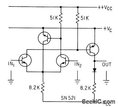
Designed as line or capacitance driver, but is same as basic gate except for output stages. Pnp transistors are hybrid, while other parts are on monolithic chip.-S. T. Robertson, Integrated Circuit Line Driver, Motorola Application Note AN-187, Aug. 1965. (View)
View full Circuit Diagram | Comments | Reading(1975)
D_C_OPERATIONAL_AMPLIFIER
Published:2009/7/16 3:58:00 Author:Jessie
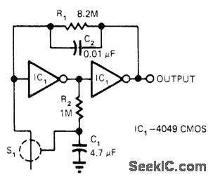
Open-loop voltage gain is 62 db, input impedance is 18,000 ohms differential and 10,000 ohms to ground, and output impedance is 8,000 ohms.-Operational Amplifiers are Getting Smaller, Electronics, 35:52, p 66. (View)
View full Circuit Diagram | Comments | Reading(642)
EXCLUSIVE_OR_CIRCUIT
Published:2009/7/16 3:58:00 Author:Jessie

Used in tester that shows computer memory performance under marginal drive currents by plotting shmoo curves. Memory error triggers single-shot and changes direction of Y generator from positive to negative along top of shmoo curve, and from negative to positive along bottom. Transistors are 2N706 and diodes ore 1N921.-J. E. Gersbach, The Great Shmoo Plot: Testing Memories Automatically, Electronics, 39:15, p 127-134. (View)
View full Circuit Diagram | Comments | Reading(843)
144_MHz_TO_14_MHz
Published:2009/7/16 3:58:00 Author:Jessie

Oscillator uses 43.333-MHz overtone-cut crystal feeding class A tripler that injects 130-MHz signal into gate of MPF-102 mixer for combining with 144-MHz output of IGFET BF amplifier to give 14 MHz for amateur-band or general-coverage receivers. Article covers construction and alignment, including de-tailed coil-winding data. -C. Klinert, A Two Meter Converter, 73 Magazine, Sept. 1973, p 65-67. (View)
View full Circuit Diagram | Comments | Reading(2795)
ANALOG_TO_DIGITAL_CONVERTER_CIRCUIT
Published:2009/7/13 3:25:00 Author:May

A working circuit that uses a PC parallel port to receive data from a 10-bit analog-to-digital converter (ADC) (Texas Instruments TLV1549) is shown. A fourth wire for reset can be powered from a logic-level signal. In fact, if your printer port produces 5 V (not all do), you can use the more-common TLC1549. Resistor RI reduces transmission errors by isolating the ADC from the cable capacitance; it might be unnecessary if the cable is short. (View)
View full Circuit Diagram | Comments | Reading(995)
TOUCH_SWITCH_USES_TIMER
Published:2009/7/13 3:24:00 Author:May
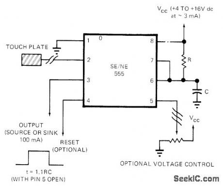
Free-running or mono capabilities of Signetics 555 timer can be controlled through choice of trigger and reset inputs, Characteristics of output pulses can be adiusted over timing periods ranging from microseconds to hours. With 5-V supply, output is TTL-compatible and current drain of only 3 mA perrnhs battery operation. Circuit is easily triggered by voltage differential between floating (ungrounded) human body and timer itself.Touch plate can be any conducting material, with virtually no size limitation. Once triggered by momentary touch, device cannot be retriggered until it has timed out. Duration of output pulse depends on RC time constant and on control voltage. Applications include switchless keyboards, burglar alarms, and bouncefree switches.-J. C. Heater, Monolithic Timer Makes Convenient Touch Switch, EDN Magazine, Dec. 1, 1972, p 55. (View)
View full Circuit Diagram | Comments | Reading(759)
TV_LINE_DECODER_II
Published:2009/7/13 3:24:00 Author:May
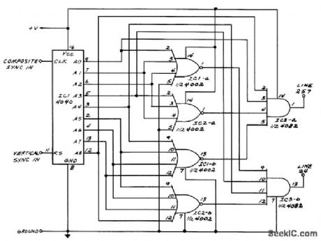
This circuit will produce outputs on TV channels 24 and 25.It was used in a decoder circuit. Ituses a CMOS counter and gate logic. (View)
View full Circuit Diagram | Comments | Reading(1258)
COIN_TOSSER
Published:2009/7/13 3:23:00 Author:May

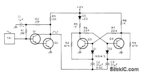
Finger on touch plate TR1 feeds stray 60-Hz sine wave (picked up by body capacitance) to high-impedance Darlington pair Q1-Q2 for squaring. Output drives flip-flop Q3-Q4. LED conducts only when Q3 is on. Removal of finger leaves LED eitheron or off with random probability. Players can try in turn to match, play odd-man-buys, or play odd-man-out. For faster results, circuit can be duplicated so each player has own touch plate. Practically any transistor types can be used, as circuit is not criti-caL-J. H. Everhart, The Coffee Flipper, 73Magazine, Nov. 1976, p 162-163. (View)
View full Circuit Diagram | Comments | Reading(1242)
CONVEYOR_MONITOR
Published:2009/7/13 3:23:00 Author:May


Will shut down conveyor line rapidly to prevent catastrophic jam, while ignoring small self-clearing pileups. Each time light beam is interrupted, light-activated scr is briely commutated by a-c line. C1 starts to charge but is shorted to zero as light is restored. If light path is blocked more than a few millisec, C1 continues to charge and fires SCR1 to stop conveyor.- Silicon Controlled Rectifier Manual, Third Edition, General Electric Co.1964, p 214. (View)
View full Circuit Diagram | Comments | Reading(843)
20W fluorescent lamp electronic ballast with with MJE13005×2 circuit diagram
Published:2011/8/4 20:04:00 Author:Rebekka | Keyword: electronic ballast, 20W fluorescent lamp
View full Circuit Diagram | Comments | Reading(3522)
FINGERTIP_SIZE_SERVO_AMPLIFIER
Published:2009/7/16 3:58:00 Author:Jessie
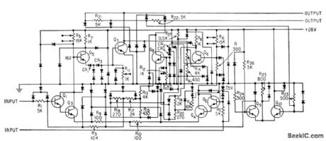


Direct-coupled class A servo amplifier diffused into 0.75-inch.diameter silicon wafer gives power output of 1.5 w and overall closed-loop gain of 200. Distributed diode planes are introduced by substrate,-M. W. Aarons, Putting a Servo Amplifier on a Small Silicon Wafer, Electronics, 35:52, p 33-35. (View)
View full Circuit Diagram | Comments | Reading(650)
TV_LINE_DECODER_I
Published:2009/7/13 3:21:00 Author:May

This circuit will produce outputs on TV lines 24 and 257. It was used for a decoder circuit. It uses a CMOS counter and gate logic. Only one pin is used for the output line indicator. (View)
View full Circuit Diagram | Comments | Reading(647)
AUDIO_POWER_AMPLIFIER
Published:2009/7/16 3:56:00 Author:Jessie

MC1524 chip gives high efficiency, low distortion, and wide range along with highest output power per mitted by dissipation of TO-5 case. Chip is combined with superior power-handling of standard bottom-collector output transistors to give monobrid amplifier providing 1 w to speaker. True class-B output circuitry gives low standby current, with crossover distortion of class B minimized by using current source Q3-Q4 for quad Q5-Q6-Q7-Q8. Diode D2 further reduces crossover distortion.-R. A. Hirschfeld, Audio Power Applications Using Integrated Circuits, Motorola Application Note AN-162, Aug. 1965. (View)
View full Circuit Diagram | Comments | Reading(0)
ALPHANUMERIC_PAGER_DECODER
Published:2009/7/13 3:20:00 Author:May
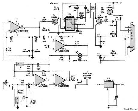
This pager decoder interfaces a scanner plugged into J1 with a personal computer's serial port via the DB25 connector. Software is necessary and can be obtained from the Internet at http://cylexinc.com/download.htm. (View)
View full Circuit Diagram | Comments | Reading(919)
TICK_TACK_TOE_MEMORY
Published:2009/7/16 3:56:00 Author:Jessie
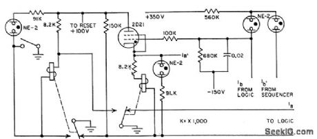
Nine memory cells are used, one for each position on game board. Circuit shown is for position No. 1. Operator moves are entered into board by pushbuttons on display panel, energizing self-latching relays of memory. Board moves are determined by a separate logic section that triggers thyratron of memory and energizes relay. Neon lamps indicate when each position is filled, and by whom.-C. E. Hendrix and R, B. Purcell, Neon Lamp Logic Gales Play Tick-Tack-Toe, Electronics, 31:25,p 68-69. (View)
View full Circuit Diagram | Comments | Reading(938)
CORES_ACTUATE_RELAY
Published:2009/7/13 3:18:00 Author:May
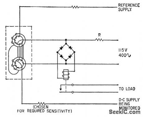


When d-c supply voltage equals reference voltage, no direct current flows through the control windings of saturable reactors, reactance of 400-cps winding is high, and voltage across rectifier bridge is high enough to pull in relay. When supply voltage increases or decreases, difference voltage causes core saturation that reduces reactance, allowing relay to drop out. Neon indicator lamp may be used in place of rectilfier bridge.-M. C. Herzig and D. C. Colbert, Voltage Monitor Needs Only Two Saturable Cores, Electronics, 36:23, p50-51. (View)
View full Circuit Diagram | Comments | Reading(670)
BASIC_IC_GATE
Published:2009/7/16 3:56:00 Author:Jessie

Circuit is basic element of current mode logic family. If reference voltage VBB is supplied to one side of gate, constant current that normally Bows through 1.24 K emitter resistor can be switched from one side of gate to other by switching input signals above and below reference voltage. Complementary output is provided from single gate.-S. T. Robertson, Integrated Circuit Line Driver, Motorola Application Note AN-187, Aug. 1965. (View)
View full Circuit Diagram | Comments | Reading(610)
PACKET_RADIO_TUNING_INDICATOR
Published:2009/7/13 3:16:00 Author:May

The tuning indicator is simply two identical tone decoders adjusted to different frequencies that share a power supply. When a decoder receives a signal of the right frequency, it lights its LED. Simply tune the circuit so that both LEDs illuminate. (View)
View full Circuit Diagram | Comments | Reading(912)
| Pages:714/2234 At 20701702703704705706707708709710711712713714715716717718719720Under 20 |
Circuit Categories
power supply circuit
Amplifier Circuit
Basic Circuit
LED and Light Circuit
Sensor Circuit
Signal Processing
Electrical Equipment Circuit
Control Circuit
Remote Control Circuit
A/D-D/A Converter Circuit
Audio Circuit
Measuring and Test Circuit
Communication Circuit
Computer-Related Circuit
555 Circuit
Automotive Circuit
Repairing Circuit
