Basic Circuit
TICK_TACK_TOE_MEMORY
Published:2009/7/16 3:56:00 Author:Jessie | From:SeekIC

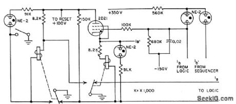
Nine memory cells are used, one for each position on game board. Circuit shown is for position No. 1. Operator moves are entered into board by pushbuttons on display panel, energizing self-latching relays of memory. Board moves are determined by a separate logic section that triggers thyratron of memory and energizes relay. Neon lamps indicate when each position is filled, and by whom.-C. E. Hendrix and R, B. Purcell, Neon Lamp Logic Gales Play Tick-Tack-Toe, Electronics, 31:25,p 68-69.
Reprinted Url Of This Article:
http://www.seekic.com/circuit_diagram/Basic_Circuit/TICK_TACK_TOE_MEMORY.html
Print this Page | Comments | Reading(3)

Article Categories
power supply circuit
Amplifier Circuit
Basic Circuit
LED and Light Circuit
Sensor Circuit
Signal Processing
Electrical Equipment Circuit
Control Circuit
Remote Control Circuit
A/D-D/A Converter Circuit
Audio Circuit
Measuring and Test Circuit
Communication Circuit
Computer-Related Circuit
555 Circuit
Automotive Circuit
Repairing Circuit
Code: