Circuit Diagram
Index 708
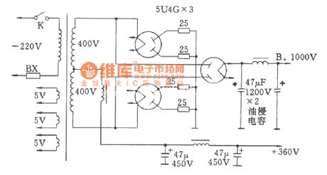
Tube High-voltage Rectifier Bridge Circuit
Published:2011/7/17 20:54:00 Author:Felicity | Keyword: Tube, High-voltage Rectifier, Bridge Circuit
View full Circuit Diagram | Comments | Reading(1891)
SIMPLE_FOUR_DIGIT_DVM_BASIC_CIRCUIT
Published:2009/7/13 4:05:00 Author:May

This circuit is designed around a Harris Semiconductor AD converter/LED display driver IC. The power supply is ±5 V. (View)
View full Circuit Diagram | Comments | Reading(2326)
HIGH_IMPEDANCE_PARAMETRIC_AMPLIFIER
Published:2009/7/13 4:05:00 Author:May
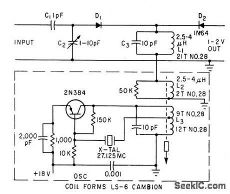
Wide-band amplifier uses diode biased with r-f to give 40-db gain. Input impedance is above 10 gigohms, and frequency response is within 3 db from 3 cps to 200 kc. Diode D1 is energy storage element. Crystal-controlled transistor oscillator is pump frequency source.-D. Rovefi, Diode Amplifer Has Ten.Gigohm Input Impedance, Electronics, 34:51, p 38-40. (View)
View full Circuit Diagram | Comments | Reading(1224)
CARBON_MONOXIDE_DETECTOR
Published:2009/7/13 4:03:00 Author:May

This circuit has a focused optical sensor to transmit light to the CO reagent, and then sense the amount of light reflected. The reagent for CO detection darkens from a light yellow color when exposed to CO. According to the card's manufacturer, a concentration as low as 100 parts per million (ppm) will darken the detector after 15 to 45 min. A concentration of 600 ppm will darken it in 1 to 2 min. The reagent will return to its original color when the air freshens, usually after about 10 min.The time it takes for the reagent to return to its original color depends on the concentration of CO to which it was exposed. The brain of the CO detector circuit is a PIC16C71 microcontroller (IC2) that contains a built-in four-channel analog-to-digital converter. Other than the microcontroller, the main component of this circuit is MOD1, an Omron BE-SY148 optical reflector module. The module directs infrared light to the CO reagent and then receives the light reflected back to it. When CO is present, the reagent will darken, thus reducing the reflectivity. The reduction is sensed by the microcontroller, which then turns on buzzer BZ1. (View)
View full Circuit Diagram | Comments | Reading(3922)
ISOLATED_INTEGRATOR_IN_100_CPS_PHASESHIFT_OSCILLATOR
Published:2009/7/16 4:20:00 Author:Jessie

Frequency can be adjusted over limited range with 500-ohm rheostat, which can easily be replaced with photocell or other resistive transducer to give frequency that varies with light intensity, temperature, voltage, current, or other parameter.-B. M. Van Emden, The Isolated-Integrator Network, EEE, 12:5, p 55-57. (View)
View full Circuit Diagram | Comments | Reading(544)
MEASURING_MAGNETIC_CHARACTERISTICS
Published:2009/7/16 4:19:00 Author:Jessie
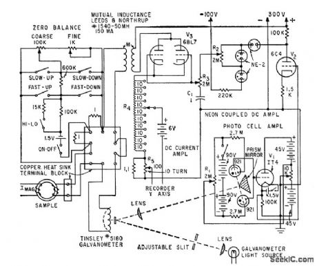
Provides rapid and accurate record of d-c magnetization and hysteresis characteristics of materials.-R. R. Bockemuehl and P. W. Wood, Industrial Hysteresigraph Uses D-c Integration, Electronics, 33:13, p 70-71. (View)
View full Circuit Diagram | Comments | Reading(664)
PLATE_CATHODE_FOLLOWER
Published:2009/7/13 4:03:00 Author:May

Has low output impedance, good gain stability, wide response, and low distortion, making it ideal as bridge driver for Wien-bridge oscillator.-K. H. Liu, Plate-Cathode Follower Wien-Bridge Oscillator, EEE, 11:2, p 27. (View)
View full Circuit Diagram | Comments | Reading(806)
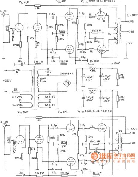
Stereo Power Amplifier Circuit
Published:2011/7/17 20:59:00 Author:Felicity | Keyword: Stereo, Power Amplifier, Circuit
View full Circuit Diagram | Comments | Reading(1067)
ENLARGER_TIMER
Published:2009/7/13 4:03:00 Author:May

Requires no transformertype power supply because circuit operates from 1 mA taken from AC line through 10K resistor and rectifier. Ferranti ZN1034E timer IC generates delay and supplies 5 V for 4001 CMOS gates. Triac is tfiggered with 100-μs 60-mA pulses at zero-crossing point. Logarithmic timecontrol pot may be calibrated from 1 to 120 s.Choose triac tohandle current drawn by enlaigher lamp used.-M.J.Mayo,Transformerless Enlarger Timer,Wireless World,May 1978,p 68. (View)
View full Circuit Diagram | Comments | Reading(0)
ELECTRICAL_READOUT_INTEGRATOR
Published:2009/7/16 4:19:00 Author:Jessie

Use of solion diode eliminates need for sensitive electrometer. Integral may be read continuously while integration is taking place, without affecting its value. Varistor is used in parallel with meter to compensate for temperature changes.-R. N. Lane and D. B. Cameron, Current Integration with Solion Liquid Diodes, Electronics, 32:9, p 53-55. (View)
View full Circuit Diagram | Comments | Reading(642)
WWV_REGENERATIVE
Published:2009/7/16 4:18:00 Author:Jessie
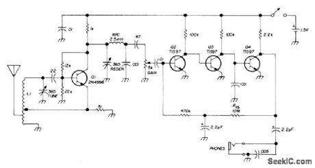
Tunes from 4.7 to 15.5 MHz, covering three WWV frequencies, 20- and 40-meter amateur bands, and several foreign broadcast bands. Draws only 1.5mA from single D cell when using headphones with 2000-ohm or higher impedance. Performs well with AM, CW, or SSB. When oscillating, detector provides own BFO signal, L1 is 3.8 μH, with emitter tap 1,turn from ground. Use clip for adjusting antenna tap. Tuning requires two hands. - C.Hall, Simple Regenerative WWV Receiver, Ham Radio, April 1973, p 42-45.
(View)
View full Circuit Diagram | Comments | Reading(1195)
OIL_PRESSURE_ACTUATED_RUNNING_LIGHTS
Published:2009/7/13 4:03:00 Author:May

Motorcycles and cars that are not equipped with (automatic) day running lights can be so equipped with the present circuit. The circuit is connected to the oil-pressure indicator. When the engine is not running, the contacts of the oil-pressure sensor in the engine block are closed. When the ignition is then switched on, the oil-pressure light comes on. The potential at A is then low, and nothing happens. When the engine is running, oil-pressure builds up, whereupon the contacts open and the indicator light goes out. The potential at A is then high so that T1 comes on and the relay becomes energized. The relay contact in series with the headlights closes so that the headlight is switched on. When the engine is switched off, the relay is deenergized and the headlights go out. (View)
View full Circuit Diagram | Comments | Reading(2454)
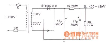
Crystal Diode Full-wave Rectifier Circuit (For Tube Amp)
Published:2011/7/17 21:19:00 Author:Felicity | Keyword: Crystal Diode, Full-wave Rectifier, Circuit, (For Tube Amp)
View full Circuit Diagram | Comments | Reading(1509)
RADAR_VIDEO_INTEGRATOR
Published:2009/7/16 4:18:00 Author:Jessie

Accepts all video and noise signals within first half of tracking gate and performs voltage -time integration. Identical integrator performs similar function for second half. Results of integrations (integrator out) go to difference detector for comparison.-D. L. Nepveux, Digital Circuits Achieve Automatic Control of Radar Range Tracking, Electronics, 34;52, p46-50. (View)
View full Circuit Diagram | Comments | Reading(684)
AIR_CONDITIONER_MONITOR
Published:2009/7/13 4:01:00 Author:May

Power for the air conditioner monitor is derived from the + 12-V power lead that feeds the magnetic clutch of the air conditioning compressor. Thus, the circuit is active only when cooling is demanded of the A/C system. The heart of the circuit is U2, a factory-calibrated three-terminal temperature-sensing IC that is designed to deliver an output voltage of 10 mY per degree Fahrenheit. The sensor, which is driven by the regulated 8-V supply, is physically attached to the A/C evap-oratorcoil return pipe so that it accurately senses the operating temperature. Its temperature-dependent output voltage, which is proportional to the sensed temperature, is fed to negative input terminal U4-a (half of an LM393N voltage comparator) at pin 2. The output of U4-a can thus be used to determine the operating temperature of the evaporator return pipe. The positive input of the comparator allows the trigger voltage level of U4-a to be set slightly higher than the normal operating temperature of the A/C evaporator return pipe, or about 0.4 to 0.5 V, represent-ing 40 to 50°F.In order to avoid a false alarm caused by the warm evaporator return pipe each time the cycling A/C compressor starts, a time delay is provided by U3, a 555 oscillator/timer connected as a one-shot or monostable multivibrator that has an output pulse width of about 25 s as determined by R3 and C4. When compressor power is applied to the monitor, U3 is automatically triggered. Once triggered, U3 generates a positive output voltage at pin 3. That causes the open-collector output transistor within U4-a to be cut off. No base current flows to Q1, and LED 2 will not light. At the end of the timed cycle of U3, U4-a is ready to monitor the evaporator temperature. Should the temperature be above the limit set by R5, the output of U4-a is pulled low, illumi-nating the warning LED (LED2). As mentioned earlier, a warm evaporator return pipe is a symptom of loss of refrigerant or other problems with the air-conditioning system. Another light-emitting diode, LED1, has been included in the circuit as a visual indication as to the operation of the air conditioner compressor. Should the refrigerant charge be extremely low, the compressor will cycle rapidly, alerting the driver to an almost total loss of refrigerant. (View)
View full Circuit Diagram | Comments | Reading(2001)
Two-channel Amplifier Circuit
Published:2011/7/17 21:00:00 Author:Felicity | Keyword: Two-channel, Amplifier, Circuit
View full Circuit Diagram | Comments | Reading(1054)
30_W_SEC_SUPPLY_WITH_CHARGER
Published:2009/7/16 4:17:00 Author:Jessie

Charges capacitor to 300 v in 8 to 12 sec through series-line voltage doubler. Battery drain is 750 mo peak and 150 ma idling. Uses transistor collector-base junction in full-wave rectifier circuit to charge nickel-cadmium battery from stepped-down ac voltage across N1 and N2. Converter operates as 120-cps square-wave switch so same transformer may be used for 60-cps charging voltage. Battery provides up to 300 flashes.-H. A. Manoogian, Transistor Photoflash Power Converters, Electronics, 31:35, p 29-31. (View)
View full Circuit Diagram | Comments | Reading(699)
Crystal Diode Bridge Rectifier Circuit (For Tube Amp)
Published:2011/7/17 21:26:00 Author:Felicity | Keyword: Crystal Diode, Bridge Rectifier, Circuit, (For Tube Amp)
View full Circuit Diagram | Comments | Reading(2227)
PRECISION_FULL_WAVE_DIODE_DETECTOR
Published:2009/7/16 4:16:00 Author:Jessie
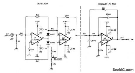
Uses opamp to reduce input voltage at which transfer curve of diode detector becomes nonlinear by factor equal to open-loop gain of opamp. Chief drawback is that delay for positive input signals, which are inverted and amplified 2 times, is twice that for composite signals. Be-VTVM cause of delay difference, signals do not subtract in phase and high-frequency performance suffers. Values shown are for test purposes, with low-pass active filter having 2-kHzcutoff.-H. Olson, Diode Detectors, Ham Radio, Jan. 1976, p 28-34. (View)
View full Circuit Diagram | Comments | Reading(1140)
DRAUGHT_DETECTOR
Published:2009/7/13 4:01:00 Author:May

The complete circuit diagram for the draught detector is shown. The key components are R2 and R4; these form a pair of identical positive-temperature-coefficient (p.t.c.) thermistors. It is essential to use this particular type of thermistor. With switch S1 on, current flows from the nominal 18-V supply to the rest of the circuit. Thermistors R2 and R4 are included in a pair of potential dividers. The first comprises fixed resistor R1 in the upper arm and thermistor R2 in the lower one. The second consists of potentiometer VR1, connected in series with fixed resistor R3, in the upper arm and thermistor R4 in the lower one. With room temperature below 60℃, the current in the thermistors will be 150 mA approximately, sufficient for them to self-heat. They will then approach the threshold temperature within a few seconds. The thermistors will stabilize when the temperature reaches about 75℃, corresponding to a resistance of some 500 Ω. In the absence of a draught, each thermistor will be surrounded by a blanket of warm air. However, therrnistor R4 is arranged so that it does not receive any draught impinging on detector R2. When a draught is detected, the warm air around R2 is disturbed, and this thermistor is cooled slightly. This results in a lower resistance and hence a falling voltage being developed across it. This sounds the alarm. R5 supplies a little hysteresis to the alarm circuit. (View)
View full Circuit Diagram | Comments | Reading(1569)
| Pages:708/2234 At 20701702703704705706707708709710711712713714715716717718719720Under 20 |
Circuit Categories
power supply circuit
Amplifier Circuit
Basic Circuit
LED and Light Circuit
Sensor Circuit
Signal Processing
Electrical Equipment Circuit
Control Circuit
Remote Control Circuit
A/D-D/A Converter Circuit
Audio Circuit
Measuring and Test Circuit
Communication Circuit
Computer-Related Circuit
555 Circuit
Automotive Circuit
Repairing Circuit
