
Circuit Diagram
Index 706
LOW_NOISE_RF_INPUT
Published:2009/7/16 4:30:00 Author:Jessie
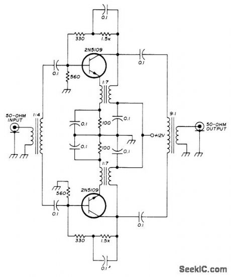
Low-noise version of transistorized push-pull RF stage uses emitter feedback through transformer to give extremely high input and output impedances. Noise figure is below 2 dB. Developed for use in high-quality communication receiver.- U. L. Rohde, Optimum Design for High-Frequency Communications Receivers, Ham Radio, Oct. 1976, p 10-25. (View)
View full Circuit Diagram | Comments | Reading(1126)
DIODE_STABILIZED_BIAS
Published:2009/7/13 4:16:00 Author:May

Posilive shunt feedback cancels shunt impedance of bitts network and transistor. RE1 is made small to obtain gain of 10; as a result, input impedance is limited to 1.5 meg. Excellent bias stability is obtained. Three diodes compensate for variations in base-emitter voltage of Q1, and negative d.c feedback from RE2 further increases bias stability. Response is flat within 3 db from 100 cps to 500 kc.-Toxas Instruments Inc., Solid-Stale Communications, McGraw-Hill, N.Y., 1966, p 184. (View)
View full Circuit Diagram | Comments | Reading(767)
FLASHING_LED_HV_SUPPLY_CIRCUIT
Published:2009/7/13 4:16:00 Author:May

When using FLEDs on a supply voltage higher than the rating of the FLED, precautions should be taken to ensure, that the device never sees a voltage above its maximum rating. (View)
View full Circuit Diagram | Comments | Reading(776)
50_MICROSEC_CLEARING
Published:2009/7/16 4:29:00 Author:Jessie
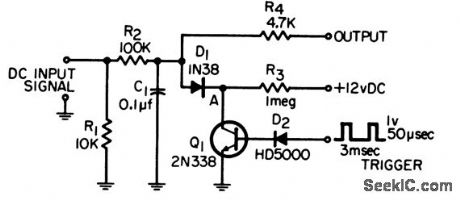
Will clear R2-C1 integrator in 50 microsec while providing isolation between integrator and switching network. Output is connected to differential amplifier for voltage level detection.-G. A. Herlich, Integrator Clearing Circuit, EEE, 14:2, p 69. (View)
View full Circuit Diagram | Comments | Reading(678)
BALLOON_TELEMETER_AND_BEACON
Published:2009/7/16 4:28:00 Author:Jessie

Delivers 10 w at 1686 kc into 72 ohms at 60% efficiency, Can also operate at 7 Mc if crystal and tank are changed.-F, W, Frykman and A. R. Moore, Lightweight Transmitter Provides Flight Data and Beacon Signal, Electronics, 34:32, p 164. (View)
View full Circuit Diagram | Comments | Reading(573)
TOUCH_BUTTONS
Published:2009/7/13 4:16:00 Author:May

Based on detecting skin resistance between two contacts built into each touch button. Contact going to 0 V would normally be metal front panel of control. Any number of sections like that in dashed lines can be cascaded to handle more buttons. A particular button always comes on when power is applied, and is canceled by next button touched. LED identifies button currently activated; use any LED rated at 20 mA. Supply can be 20 to 30 V. Outputs may be used to drive FET analog switches, varactor tuning diodes, or relays.-P. G. Hinch, Self-Cancelling Touch Button Control, Wireless World, Oct. 1974, p 380. (View)
View full Circuit Diagram | Comments | Reading(973)
ELECTRONICALLY_ADJUSTABLE_RESISTOR
Published:2009/7/16 4:28:00 Author:Jessie

Uses Memistor in which rate of change of resistance is controlled by current applied to third electrode. Resistance range is from 2 to 30 ohms. Input pulses up to 10 V are integrated by plating action in sealed Memistor cell, to give d-c output of 0 to 3 V.-Adjustable Resistor Has Built-in Memory, Electronics, 35:51, p 76-77. (View)
View full Circuit Diagram | Comments | Reading(571)
LIQUID_LEVEL_CONTROL
Published:2009/7/13 4:16:00 Author:May

Operational trigger has sufficient sensitivity even for distilled water and alcohol, to control level within 1 mm.-P. Lefferts, Operational Trigger For Precise Control, Electronics, 37:28, p50-55. (View)
View full Circuit Diagram | Comments | Reading(1297)
MULTICOLOR_LED_DRIVER
Published:2009/7/13 4:15:00 Author:May


A TLC555 CMOS timer, IC1, is configured as a square-wave generator that has an adjustable time period of about 2 to 7 s. That output drives IC2, a CD4017 CMOS Johnson counter, which provides the six decoded output steps necessary to trigger the three additive and three subtractive primary color combinations. A CD4025 CMOS triple three-input NOR gate, IC3, gates the six outputs to the proper LED current sources, thereby maintaining the correct color-mixing sequence. Four MPSA64 PNP Darlington transistors (Q1 to Q4) are configured as gated current sources, with capacitors C4 to C7 providing long time constants that allow LED1 to LED4 to ramp up and down in intensity. This allows the color changes to be continuous, rather than in six abrupt steps. Power for the circuit is provided by a 5-V supply. Transformer T1 steps down the voltage from a wall outlet to 6.3 Vac, recti-fied by BR1 and regulated by IC1, a 78L05. (View)
View full Circuit Diagram | Comments | Reading(1737)
MULTIDIGIT_DEMONSTRATION_COUNTER
Published:2009/7/13 4:14:00 Author:May

Simple interconnection of RS7490 decade counter、RS7447 decoder, and 7-segment digital display for each desired digit makes ideal counter for classroom demonstrations and Sci-ence Fair exhibits, With two additional stages added, display reaches 9999 before recycling. Use 1N914 diode in series with battery to protect against polarity reversal and reduce supply to 5 V for ICs.-F. M. Mims, Integrated Circuit Projects, vol. 6, Radio Shack, Fort Worth, TX, 1977, p53-63. (View)
View full Circuit Diagram | Comments | Reading(3462)
ZERO_CROSSING_SYNCHRONIZER
Published:2009/7/13 4:14:00 Author:May

Used to synchronize firing circuit of scr's with zero crossing points of sinusoidal a-c line voltage, to initiate new timing cycle at each zero crossing and thereby permit precise control of a-c power delivered to load. In temperature control system, circuit held liquid within 0.001℃ of set point despite wide ambient temperature range.-J. D. Reed, Zero-Crossing Sync Circuit for SCR's, EEE, 12:8, p74. (View)
View full Circuit Diagram | Comments | Reading(1683)
EEPROM_DISPLAY_DRIVER
Published:2009/7/13 4:13:00 Author:May

This circuit illustrates use of an EEPROM as a decoder and display driver. IC1 and IC2 generate a binary sequence of addresses in the EEPROM, and the data out of the EEPROM drive (IC4) and the display. (View)
View full Circuit Diagram | Comments | Reading(2511)
CRT_GRAY_SCALE_CONTROL
Published:2009/7/13 4:13:00 Author:May

Circuit provides digital selection of up to 16 shades of gray for image on screen of cathode-ray tube, as required for different imaging requirements or different photographic films. DMOS FETs provide fast switching times so data rate is limited only by TTL drive circuits. Four bits of digital data stored in 9311 memory are used for selecting desired scale. Output of circuit is used to control beam intensity. Circuit also permits complete video inversion for negative.-K. R. Peterman, Fast CRT Intensity Selector Adjusts the Gray Scale, EDN Magazine, March 20, 1976, p 98 and 100. (View)
View full Circuit Diagram | Comments | Reading(663)
UP_DOWN_COUNTER
Published:2009/7/13 4:12:00 Author:May

Cascading of 4192 de-cade up/down counters and use of two clocks give fully synchronous system for adding or subtracting count. Both clocks are normally held high. Low on up clock advances count. Low on down clock subtracts 1 from count. Clocking takes place on trailing or positive edge of neg-ative pulse. Parallel loading inputs are used to preset counter to any desired number. -D. Lan-caster, CMOS Cookbook, Howard W. Sams, Indianapolis, IN, 1977, p 309-310. (View)
View full Circuit Diagram | Comments | Reading(1453)
SOUND_CONTROLLED_LAMP
Published:2009/7/13 4:12:00 Author:May

Zero-voltage switching achieves interference-free proportional control of lamp intensity by sound source. Both inputs to AND gate IC15 must be high for triac to tum on. 0ne input is from zero-crossing detector IC1, Tr1,. and IC2, which produces 100-Hz series of positive-going pulses.Other input is provided by filterirectifier/com-parator circuit, Inverting input of comparator IC14, is fed by DAC IC14 which produces stepped ramp waveform from outputs of 7490 counter IC3. Counter is connected to count to 5 before resetting internally, giving five possible brightness levels for lamp. Opamps IC5, and IC6, detect when audio input falls below about 10 mV and then release IC7-IC9, from reset stage so the two 4-bit counters start counting 100-Hz waveform.Resetting occurs again when audio input next passes 10-mV level. Lamp automatcaUy turns on when music stops. All ICs are 741 or equivalent except as marked. Unmarked diodes are 1N4148, C1, and C2 are 100-nF polyester electrolytics, and all transistors are general-purpose types. Resistor values in table are for threechannel system,but more channels can be used if desired.-A. R. Ward, Sound-to Light Unit, Wireless World, July 1978, p 75.
(View)
View full Circuit Diagram | Comments | Reading(1014)
AC_DC_SUPPLY_LED_CIRCUIT
Published:2009/7/13 4:12:00 Author:May

(a) Series resistor calculation; (b) using an LED on an ac supply. (View)
View full Circuit Diagram | Comments | Reading(704)
CASCADED_DOWN_COUNTER
Published:2009/7/13 4:12:00 Author:May

4522 decimal divide-by-N counter is used with BCD thumb-wheel switch for each decade. Output is in BCD format, going down from preset number in range of 0-99. Decoded 0 output of tens stage is connected to CF or carry-forward input of units stage. Only when both counters are in 0 state is 0 output provided. Preset number is then reloaded into counters. -D. Lancaster, CMOS Cookbook, Howard W. Sams, Indianapolis, IN, 1977, p 311-312.
(View)
View full Circuit Diagram | Comments | Reading(3636)
CHARGING_CURRENT_LIMITER
Published:2009/7/16 4:27:00 Author:Jessie

Series regulator transistor is driven by differential amplifier using npn transistors, to control charging of nickel-cadmium battery.-G. H. P. Kohnke, Simple Voltage Regulator Limits Load Current, Electronics, 37:28, p 63. (View)
View full Circuit Diagram | Comments | Reading(1483)
99_s_PROGRAMMABLE
Published:2009/7/13 4:10:00 Author:May

Line-frequency-based precision interval timer was developed for use with repeaters or photographic enlargers. Circuit is accurate to within 1/60 s. Two 10-position switches are set to desired interval. Connection to AC line gives 4-V square wave for 60-Hz clock input. Transistor type used as relay driver is not critical.-G.R. Allen, Dependable Timer, 73 Magazine, July 1976, p 84-87. (View)
View full Circuit Diagram | Comments | Reading(1421)
BOOTSTRAP_INTEGRATOR_AND_SWITCH
Published:2009/7/16 4:27:00 Author:Jessie


Circuit is part of memory and alarm system that accumulates predetermined numbers of pulses, then switches off until reset.-G. A. Dunn and N. C. Hekimian, Tube-Transistor Hybrids Provides Design Economy, Electronics, 32:23, p 68-70. (View)
View full Circuit Diagram | Comments | Reading(557)
| Pages:706/2234 At 20701702703704705706707708709710711712713714715716717718719720Under 20 |
Circuit Categories
power supply circuit
Amplifier Circuit
Basic Circuit
LED and Light Circuit
Sensor Circuit
Signal Processing
Electrical Equipment Circuit
Control Circuit
Remote Control Circuit
A/D-D/A Converter Circuit
Audio Circuit
Measuring and Test Circuit
Communication Circuit
Computer-Related Circuit
555 Circuit
Automotive Circuit
Repairing Circuit