
Circuit Diagram
Index 712
HIGH_INPUT_IMPEDANCE_FROM_100_CPS_TO_230_KC
Published:2009/7/13 3:43:00 Author:May

For transducers requiring input impedance above 1 meg. Requires only single Power supply, for direct coupling of low-level high-impedance sources. Voltage gain is stable within 0.05 db of 20 db from -25 to +125℃. Power gain is 46 db and power consumption is only 65 mw.-Texas Instruments Inc., Solid-State Communications, McGraw-Hill, N.Y., 1966, p 294. (View)
View full Circuit Diagram | Comments | Reading(540)
MAJORITY_DECISION
Published:2009/7/16 4:03:00 Author:Jessie

Balanced-pair tunnel-diode arrangement with phase-locked tank serves as gale operating on 50-Mc pump.-F. leary, Computers Today, Electronics, 34:17, p 64-94. (View)
View full Circuit Diagram | Comments | Reading(530)
DOUBLE_BALANCED_MIXER
Published:2009/7/16 4:03:00 Author:Jessie
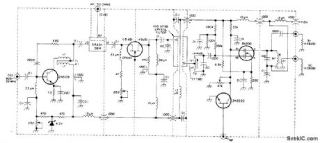
Uses grounded-gate CP643 preamp having high dynamic range,2N5109 oscillator injection amplifier, and 3N200 IF amplifier in combination with Minilabs SRA3H double-balanced mixer. Third-order intercept point is +30 dBm. Oscillator requirementis -1 to +2 dBm (200 to 280 mV across 50 ohms) AGC range is greater than 50 dB Levels shown in parentheses are for 0 dBm (224 mV) at input and zero AGC voltage.-U. L. Rohde, High Dynamic Range Receiver Input Stages, Ham Radio, Oct. 1975, p 26-31. (View)
View full Circuit Diagram | Comments | Reading(6306)
NE602_PRODUCT_DETECTOR_CIRCUIT
Published:2009/7/13 3:43:00 Author:May

This circuit uses an NE602 as a product detector. The component values depend on operating frequency and are typical for 455-kHz operation. Note that a passive RC filter is showtt in the audio output circuit. T2 acts as an oscillator coil for the 455-kHz local oscillator (or, in this case, beat frequency oscillator). (View)
View full Circuit Diagram | Comments | Reading(3875)
ABSOLUTE_DIFFERENCE_INTEGRATOR
Published:2009/7/16 4:02:00 Author:Jessie
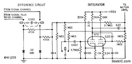
Uses two-pole chopper with capacitor connected between the two reeds. During half of chopper cycle, capacitor is charged to voltage difference between outputs of two signal-processing channels. During other half-cycle, charge is transferred to integrator circuit and positive side of capacitor is clomped to ground by one of the two diodes. Integrator is chopper-stabilized d-c amplifier with capacitive feedback, having gain of 200 and integration time constant of 1.5 hours.-H. Schwarzlander, Intelligibility Evaluation of Voice Communications, Electronics, 32:22, p 88-91. (View)
View full Circuit Diagram | Comments | Reading(557)
SLAVE_FLASH
Published:2009/7/13 3:42:00 Author:May

Remote fiashtube having no connection with camera is fired by light-activated SCR (LASCR) when triggered by main fiash of camera. Used to provide illumination at greater depth than main flash range, to soften sharp shadows, and to provide backlighting for fiash photographs. LED is indicator showing that circuit has been triggered, reminding photographer that new flash lamp should be inserted.-F.M. Mims, Transistor Projects, Vol.1, Radio Shack, Fort Worth, TX, 1977, 2nd Ed., p79-85. (View)
View full Circuit Diagram | Comments | Reading(2065)
WORD_SWITCH
Published:2009/7/16 4:02:00 Author:Jessie

Circuit is basically bilateral switch, which closes selected word circuit of memory used in Burroughs B-215 Visible Record Computer. Units and lens inputs are used to select particular word. Third input to gate is for special-purpose inhibit instruction.-G. E. Lund and D R. Faulis, Expandable Random Access Memories, Electronics, 33:11, p 164-166. (View)
View full Circuit Diagram | Comments | Reading(521)
ONE_IC_TONE_DECODER
Published:2009/7/13 3:42:00 Author:May

This circuit can be used in a receiver or a repeater to require that a tone be present on a received signal so as to unsquelch the receiver. (View)
View full Circuit Diagram | Comments | Reading(504)
INTEGRATOR_AND_BINARY_TRIGGER_FOR_SHMOO_PLOTTER
Published:2009/7/16 4:02:00 Author:Jessie
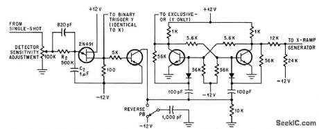
Integrator stage with R2-C2 measures duty cycle of single-shot mvbr used in showing computer memory perform once under marginal drive currents. Binary triggers control direction of ramp generators und increase or decrease memory drive current. Npn transistors are 2N706 and diodes are 1N921.-J. E. Gersbach, The Great Shmoo Plot: Testing Memories Automatically, Electronics, 39:15, p 127-134. (View)
View full Circuit Diagram | Comments | Reading(635)
BCD_DECODER_DRIVER_CIRCUIT
Published:2009/7/13 3:41:00 Author:May
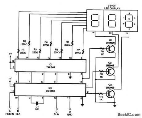
The BCD decoder-driver circuit will interface with any standard BCD output to produce a digital display. (View)
View full Circuit Diagram | Comments | Reading(1221)
RTTY_TONE_DECODER
Published:2009/7/13 3:40:00 Author:May


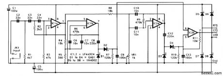
The full circuit diagram for the RTTY tone decoder is shown. The input filter is based on IC1a, and it is a third-order (18 dB per octave) high-pass type with a cutoff frequency at approximately 750 Hz. IC1b is used in the higher-frequency bandpass filter. Capacitor C8 couples the output of this filter to a conventional half-wave rectifier and smoothing network based on diodes D1 and D2. The time constant of R7 and C9 is long enough to give a well-smoothed output signal, but short enough to permit the unit to respond rapidly as the input signal alternates between one tone and the other. The second bandpass filter is based on IC2a and is essentially the same as the first, but it has a preset resistor (VR1) as one section of the input attenuator. This enables the center frequency of the filter to be adjusted, but (in operation) it is set 170 Hz lower than the center frequency of the other filter. If preferred, preset potentiometer VR1 can be set to give a center frequency 170 Hz higher than the other filter. It can also be set for shifts of other than 170 Hz.The output of IC2a (pin 1) feeds into a rectifier and smoothing circuit that is identical to the one used at the output of the other filter.The outputs of both the smoothing circuits drive the inputs of IC2b, which acts as the voltage comparator. A small amount of dc positive feedback is provided by resistor R11, and this helps to avoid problems with jitter at the output when only background noise is present at the input. Power is obtained from two of the otherwise unused handshake outputs of the PC's serial port. Diodes D5 to D8 form a bridge rectifier that ensures that the circuit is always provided with a supply of the correct polarity. Only a milliampere or two can be drawn from the handshake outputs. Accordingly, IC1 and IC2 must be low-supply-current operational amplifiers. (View)
View full Circuit Diagram | Comments | Reading(1573)
RINGING_TYPE_PULSE_GENERATOR
Published:2009/7/16 4:02:00 Author:Jessie
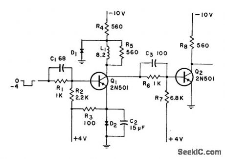
Used in some large high-speed computers to transmit pulses from central unit over long distances as d-c levels, then convert back to pulse forms. To convert level back to pulse, transistor switch is fumed off by positive-going wave front energizing ringing circuit. Input triggering of ringing stage is accomplished when definite threshold level is exceeded.-Pulse Generator for High-Speed Computers, Electronic Circuit Design Handbook, Mactier Pub. Corp., N.Y., 1965, p 75. (View)
View full Circuit Diagram | Comments | Reading(733)
SWEPT_OSCILLATOR_FOR_HAM_BAND_ANTENNA_TUNING
Published:2009/7/13 3:39:00 Author:May

Transistor Q1 acts as a constant-current generator, charging capacitor C1 at a rate determined by the value of R1. The high input impedance of U1b ensures that the constant-current generator is not excessively loaded and forwards the voltage level of C1 to U1c. U1c is configured as a comparator, and output pin 8 goes low when pin 9 rises above 9 V. This switching action applies a trigger pulse via capacitor C2 to activate the monostable multivibrator, U2. The resulting high pulse from pin 3 of U2 provides a discharge path for capacitor C1 through turned-on transistor Q2. A continuous sweep ramp with reset is produced at pin 7 of Ulb at a rate determined by RIC1 (approximately 75 Hz). The swept oscillator section consistsof a dual-gate MOSFET transistor in a Colpitts configuration, followed by a buffer amplifier that provides the RF from the selected frequency range to an output amplifier and short antenna. As the output sawtooth waveform from U2, pin 7, is applied to the varactor, the capacitance of the tank circuit decreases from approximately 62 pF at the low end of the ramp to a very low value at the maximum sweep level of about 9.2 V. The on-off switching action of the sweep waveform modulates the generated RF to produce an obnoxious buzz, which is easy to differentiate from other low-level signals at the selected receiver frequency when adjusting the tuner or antenna.
(View)
View full Circuit Diagram | Comments | Reading(1031)
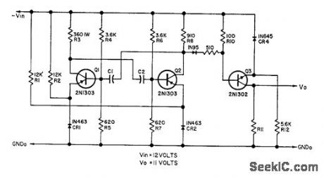
HIGH_GAIN_AMPLIFIER
Published:2009/7/16 4:01:00 Author:Jessie

Integrator amplifier using ten silicon transistors in five voltage gain stages gives gain of 250,000. To prevent saturation by spurious microvolt signals, input network is shielded by Mu-metal can grounded to signal ground and overall steel can grounded to power ground. Power supply ripple must be below 0.01%. Amplifier drives 6.w ac servomotor having d-c tachometer on same shaft.-S. T. Cop and N. P. White, Guidance Systems in Manned Space Flight, Electronics, 32:33, p 49-51. (View)
View full Circuit Diagram | Comments | Reading(0)
BISTABLE_AND_CIRCUIT_WITH_RESET
Published:2009/7/16 4:01:00 Author:Jessie
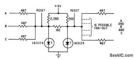
Uses resistance-coupled inputs to tunnel diodes. Gate is open when 1N3l29 is on its negative-resistance slope, so reset pulse must be applied to close if.-F. Leary, Computers Today, Electronics, 34:17, p 64-94. (View)
View full Circuit Diagram | Comments | Reading(499)
R_C_SERVO_SWEEP_DRIVER_CIRCUIT
Published:2009/7/13 3:37:00 Author:May

The circuit shown produces a ramp that can be used to modulate the threshold of another 555 timer, which is configured to generate the pulse signal to drive the R/C servo. In this way, the servo can be slowly moved through a desired angle. Note that for long time constants, R6 and R7 will be large. Therefore, C2 should be a low-leakage capacitor, or a CMOS timer (7555) can be used to permit larger resistances and smaller capacitors to be used. (View)
View full Circuit Diagram | Comments | Reading(690)
VARIABLE_SQUARE_WAVES
Published:2009/7/16 4:01:00 Author:Jessie
Output is adjustable from 0.5 cps to 60 kc at currents up to 150 ma, without appreciable corner rounding of waveform, with variable pulse width and variable interval between pulses, for driving flash lamps, relays, and computer pales.-J. D. Reed, Square Wave Generator with Variable On and Off Times, EEE, 10:10, p 27-28. (View)
View full Circuit Diagram | Comments | Reading(702)
DTMF_RECEIVER_DECODER
Published:2009/7/13 3:36:00 Author:May

This decoder uses a G8870 DTMF receiver decoder chip to decode DTMF signals and drive individual outputs via a 4028 binary-decimal decoder. Xtal is a 3.579-MHz TV burst crystal. C1=C2=0.1μF, R1=R2=100 kΩ and R3=300 kΩ. D1 through D4 are small red LEDs. (View)
View full Circuit Diagram | Comments | Reading(3425)
2_METER_SINGLE_VMOS
Published:2009/7/16 4:00:00 Author:Jessie
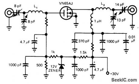
Provides 5-W PEP output at 146 MHz, with noise figure of only 2.35 dB. Developed for amateur radio applications. Uses Siliconix VN65AJ transistor. - E. Oxner, Will VMOS Power Transistors Replace Bipolars in HF Systems? , EDN Magazine, June 20, 1977, p71-75.
(View)
View full Circuit Diagram | Comments | Reading(651)
MOTOR_TRANSIENT_ANTICIPATOR
Published:2009/7/13 3:36:00 Author:May

Disconnects battery supply of sensitive counters for preset interval during switching period of nearby air conditioner, to avoid extraneous counts by switching transients from compressor motor and control relays.-C. H. Harris, Motor Transient Anticipator, EEE,13:5, p45-46. (View)
View full Circuit Diagram | Comments | Reading(620)
| Pages:712/2234 At 20701702703704705706707708709710711712713714715716717718719720Under 20 |
Circuit Categories
power supply circuit
Amplifier Circuit
Basic Circuit
LED and Light Circuit
Sensor Circuit
Signal Processing
Electrical Equipment Circuit
Control Circuit
Remote Control Circuit
A/D-D/A Converter Circuit
Audio Circuit
Measuring and Test Circuit
Communication Circuit
Computer-Related Circuit
555 Circuit
Automotive Circuit
Repairing Circuit