
Circuit Diagram
Index 716
LATCHING_TOUCH_SWITCH
Published:2009/7/13 3:05:00 Author:May

Uses LED as status display that substitutes for tactile feel of ordinary pushbutton switch. In reset state, LED is off. When touch contacts are bridged by resistance of finger, flip-flop changes state and LED comes on while output changes to high state.-V. Gregory, CMOS Touch Switches-Convenient, Less $ and Sexy, EDN Magazine, May 5, 1976, p 112. (View)
View full Circuit Diagram | Comments | Reading(897)
VOLTAGE_CONTROLLED_AMPLIFIER_STAGE
Published:2009/7/13 3:05:00 Author:May
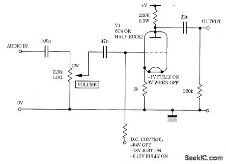
Gain is controlled by a variable negative grid bias in this amplifier stage. (View)
View full Circuit Diagram | Comments | Reading(649)
90_VRMS_AT_500_W
Published:2009/7/13 3:05:00 Author:May

Open-loop RMS voltage regulator acts with full-wave bridge to provide good AC voltage regulation for AC load over line voltage range of 110-130 VAC. As input voltage increases, voltage across R10 increases andserves to increase firing point of PUT Q3. This delays firing of SCR Q5 to hold output voltage fairly constant as input voltage increases. Delay network of Q1 prevents circuit from latching up at beginning of each charging cycle for C1.-R.J. Haver and B.C. Shiner,″Theory,Characteristics and Applications of the Programmable Unijunction Transistor, Motorola,Phoenix,AZ,1974,AN-527,p 11. (View)
View full Circuit Diagram | Comments | Reading(1709)
DATA_ENTRY
Published:2009/7/13 3:04:00 Author:May
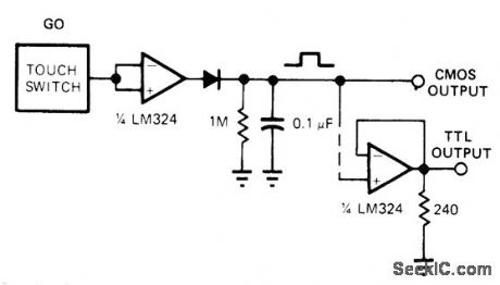
Touch of operator's finger on input button produces CMOS output. Addition of one opamp section gives TTL output. Touch button can be 0.5-inch-square copper-clad pattern on printed-circuit board or machine-screw head having comparable area. For proper switching, circuit must connect to line-operated DC power supply.-R. D. Wood, Replace Bulky Mechanical Switches with Touch Controls, EDN Magazine, April 20, 1978, p 132-133. (View)
View full Circuit Diagram | Comments | Reading(816)
SINGLE_ENDED_HI_Fl_AMPLIFIER
Published:2009/7/13 3:04:00 Author:May
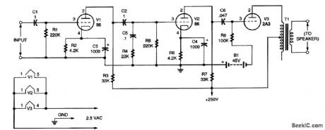
The circuit as shown will handle up to about 0.5 V; above that, distortion will be present. The input stage amplifies the signal voltage about seven times, and the second stage amplifies the voltage about 10 times. Both stages use type 56 triodes (V1 and V2). The output stage uses a type 2A3 tube, V3. Two 22.5-V batteries wired in series (B1) were used to provide 45 V on the grid of V3. In this circuit (and other single-ended amplifiers), direct current flows in the primary of the output transformer (T1) to use the circuit modification shown in Fig. 2. That change keeps dc out of the primary at some sacrifice in power. With the modification, the amplifier will be flat (within 1 dB) from 20 to 20,000 Hz. (The modified circuit requires that a high-voltage transformer be used in the power-supply circuit.) Note that transformer T1 is shown connected from one end of the primary to the center tap. That was done because it is assumed that the transformer used will have a primary impedance of about 8000 Ω. The recommended load for a 2A3 tube (V3) is 2500 Ω for maximum output, but increasing the impedance lowers the distortion while only slightly lowering the power. (View)
View full Circuit Diagram | Comments | Reading(759)
UNDERCURRENT_OVERCURRENT_PROTECTION
Published:2009/7/13 3:04:00 Author:May

Guards against improper operation of control amplifier in nucelor reator scram system.If rod currents vary beyond predetermined limits circuit initiates reactor scram.Either transistor may open relay coil circuit.-E.J.Wade and D.S.Davidson.How Transistor Circuits Protect Atomic Reactors,Electronics.31:29.p73-75. (View)
View full Circuit Diagram | Comments | Reading(968)
MAIN_GATE_MVBR_WITH_DIODE_LIMITER
Published:2009/7/16 10:19:00 Author:Jessie

Diode-connected triode in parallel with output tube plate limits positive swing at this point. Circuit is triggered by blocking-oscil-lator pulse through normally-on tube cathode resistor.-NBS, Handbook Preferred Circuits Navy Aeronautical Electronic Equipment, Vol. 1, Electron Tube Circuits, 1963, p N10-4. (View)
View full Circuit Diagram | Comments | Reading(779)
TOUCH_SWITCH_1
Published:2009/7/13 3:03:00 Author:May

Performs function of switch by means of relay contacts when SCR is triggered by placing finger on touch plate. Values shown keep relay energized for 5-10 s after touch. Developed as replacement for switchtype controls on amateur radio receiver. Once SCR has fired, it conducts until charge on 1000-μF capacitor decreases enough to drop SCR current below minimum for conduction.-J. J. Schultz, Rapid Receiver Control Switching, 73 Magazine, Dec. 1973, p 67-69. (View)
View full Circuit Diagram | Comments | Reading(0)
200_400_AND_800_PPS_PRF_GENERATOR
Published:2009/7/16 10:18:00 Author:Jessie

Used in airborne radar. Frequency stability is 3% for 200 pps and 8% for higher frequencies, One drawback of mvbr here is that output impedance equals plate load resistance, which must be relatively high for good frequency stability.-NBS, Handbook Preferred Circuits Navy Aeronautical Electronic Equipment, Vol. 1, Electron Tube Circuits, 1963, p N5-1. (View)
View full Circuit Diagram | Comments | Reading(634)
CHOKE_CONTROLLED_ONE_SHOT
Published:2009/7/16 10:17:00 Author:Jessie

Provids output pulses longer in duration than input trigger. Can be triggered by either negative or positive pulse. –W. M. Carey,Using Inductive Control in Computer Circuits, Electronics, 32:38, p 31-33. (View)
View full Circuit Diagram | Comments | Reading(456)
SIMPLE_MMIC_AMPLIFIER_CIRCUIT
Published:2009/7/13 3:03:00 Author:May
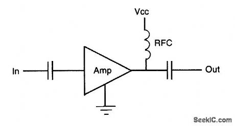
This is the simplest implementation of an MMIC amplifier. (View)
View full Circuit Diagram | Comments | Reading(537)
12_V_REGULATOR_FOR_GTL_TERMINATION
Published:2009/7/13 3:02:00 Author:May
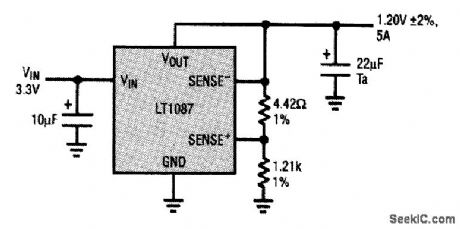
A recent development in high-speed digital design has resulted in a new family of logic chips called gunning transition Logic (GTL). These chips use high-speed logic and require active termination for best interconnection performance. The termination voltage required is 1.2 V, and the input voltage can be as low as 3.3 V from a logic supply. The LT1087 5-A low-dropout regulator shown here addresses these requirements by providing a regulated 1.2-V ±2 percent output voltage from a minimum 2.7-V input. Note that the LT1087 has a 1.25-V reference, but provides Kelvin sensing inputs for the feedback amplifier. The 4.42-Ω resistor is inserted as a simple way to adjust the internal reference downward without sacrificing regulation. This GTL termination circuit supplies 5 A maximum load current and can handle 3.3-, 5-V, or higher supplies, although 3.3 V is recommended for minimum device dissipation. (View)
View full Circuit Diagram | Comments | Reading(816)
NOISE_SUPPRESSION
Published:2009/7/16 10:16:00 Author:Jessie

Diode in collector circuit makes monstable mvbr immune to most noise pulses.-B. D. Simmonds, Diode Quiets Input to Monostable Multi, Electronics, 38:19, p 99-100. (View)
View full Circuit Diagram | Comments | Reading(789)
MMIC_AMPLIFIER_CIRCUIT
Published:2009/7/13 3:02:00 Author:May
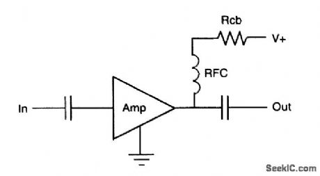
The addition of a series dropping resistor allows operation at higher supply voltages. (View)
View full Circuit Diagram | Comments | Reading(617)
DIRECT_CONVERSION
Published:2009/7/16 7:07:00 Author:Jessie
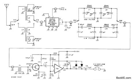
Simple direct-conversion amateur receiver uses VFO and mixer to produce AF signal directly, with no IF amplifier or second detector. For SSB reception, VFO is tuned to frequency of suppressed carrier. For CW, VFO is detuned enough to give note of desired pitch. Not suitable for AM or FM reception. Separate input tuned circuits are used for 15-40 meters and for 80-160 meters. Use ferrite or powdered iron toroid cores for coils, with turns determined experimentally. L7 and L8 are 88-mH toroids with series-connected windings. R1 is used to attenuate strong signals. Article gives circuit for VFO and buffer amplifier. Separate VFO is used for each band (160, 80, 40, 20, and 15 meters). Construction details are given, along with advantages and drawbacks of direct conversion.-D. Rollema, Direct-Conversion Receiver, Ham Radio, Nov. 1977, p 44-55. (View)
View full Circuit Diagram | Comments | Reading(1181)
TOUCH_SWITCH
Published:2009/7/13 3:01:00 Author:May

Uses NE-77 neon lamp, which is similar to NE-2 but has third electrode for triggering. When person touches metal sensor plate of switch, AC voltage picked up by body is applied to trigger electrode of neon, making it fire and energize 5000-ohm relay K1 (Potter & Brumfield RS5D or equivalent). Relay remains energized until S2 is opened to reset circuit. Adjust R1 so voltage applied to center electrode of V1 is just below trigger point.-J. P. Shields, How to Build Proximity Detectors & Metal Locators, Howard W.Sams, Indianapolis, IN, 2nd Ed., 1972, p 52-55. (View)
View full Circuit Diagram | Comments | Reading(0)
PUSH_PULL_RF
Published:2009/7/16 7:06:00 Author:Jessie

Uses VHF power transistors to obtain wide dynamic range. Transformers are trifilar wound on Indiana General F625-9-T09 toroid cores. Circuit has extremely low VSWR at both input and output, along with low noise figure. Second-order intermodulation products can be suppressed nearly 40 dB over single stage. Either RCA 2N5109 or Amperex BFR95 transistors can be used. Gain is about 11 dB.Current feedback is used through unbypassed 6.8-ohm emitter resistor, voltage feedback through unbypassed 330-ohm base-to-collector resistor, and transformer feedback through third winding on wideband transformer to stabilize input and output impedances.-U. L.Rohde, High Dynamic Range Receiver Input Stages, Ham Radio, Oct. 1975, p 26-31. (View)
View full Circuit Diagram | Comments | Reading(1085)
RF_INPUT_STAGE
Published:2009/7/16 7:01:00 Author:Jessie

Push-pull transistorized RF stage for communication receiver uses voltage and current feedback to minimize intermodulation distortion. Transformers serve to stabilize impedance. Circuit is basically constant-current device. Second-order intermodulation distortion products are suppressed almost 40 dB more than with single-transistor stage. To apply AGC, replace the two 270-ohm resistors with single PIN-diode shunt regulator.-U. L. Rohde, Optimum Design for High-Frequency Communications Receivers, Ham Radio, Oct.1976, p 10-25. (View)
View full Circuit Diagram | Comments | Reading(2110)
CAPACITANCE_TYPE_AIRCRAFT_FUEL_GAGE
Published:2009/7/16 5:49:00 Author:Jessie

Indicates weight of fuel rather than volume. Uses self-balancing bridge, with concentric-tube capacitor mounted vertically in cell of tank to serve as one arm. With fuel in tank, servo drives bridge-rebalance potentiometer and indicator to new position corresponding to amount of fuel in tank.-J. Markus and V. Zeluff, Handbook of Industrial Electronic Control Circuits, McGraw-Hill, N.Y., 1956, p 21.
(View)
View full Circuit Diagram | Comments | Reading(1470)
TOUCH_CONTROLLED_SWITCH
Published:2009/7/16 5:48:00 Author:Jessie

Normal 30 to 100-pf capacitance of human body turns lamp on and off. Touching on antenna loads high-impedance network, reducing neon-lamp oscillator voltage below level required for firing four-layer pnpn germanium alloy transistor, and current that was shunted to ground through transistor now operates relay, turning on lamp. Touching off antenna reverses all conditions. -S. B. Gray, Home and Auto Controls, Electronics, 36:19, p 52-66. (View)
View full Circuit Diagram | Comments | Reading(683)
| Pages:716/2234 At 20701702703704705706707708709710711712713714715716717718719720Under 20 |
Circuit Categories
power supply circuit
Amplifier Circuit
Basic Circuit
LED and Light Circuit
Sensor Circuit
Signal Processing
Electrical Equipment Circuit
Control Circuit
Remote Control Circuit
A/D-D/A Converter Circuit
Audio Circuit
Measuring and Test Circuit
Communication Circuit
Computer-Related Circuit
555 Circuit
Automotive Circuit
Repairing Circuit