
Circuit Diagram
Index 710
CHARGER_CONTROL_WITH_REFERENCE_BAT_TERY
Published:2009/7/16 4:11:00 Author:Jessie

Developed to insure constant d-c supply for rotary converters if ship's power supply fails. Control circuit operates SW1 at proper time intervals. B2, in series with B1 with polarity opposing, supplies reference voltage. When storage battery needs charge, gas tube ignites to pull in RL and initiate charging cycle.-V. Zeluff and J. Markus, Electronics Manual for Radio Engineers, McGraw-Hill, N.Y., 1949, p 545. (View)
View full Circuit Diagram | Comments | Reading(735)
QUASI_CONSTANT_CURRENT_BATTERY_CHARGER
Published:2009/7/16 4:10:00 Author:Jessie

Circuit monitors state of charge of battery while charging at constant high rate, then transfers automatically to constant-current trickle charge when battery is fully charged.-A. Anton, Comparator Controls Battery Charging Rate, Electronics, 37:12, p 72. (View)
View full Circuit Diagram | Comments | Reading(888)
PREFERRED_SATURATING_BISTABLE
Published:2009/7/16 4:10:00 Author:Jessie

Slow-speed mvbr may be used as counter, shift register, gate, or switch. Provides transitional stages between electromechanical readout and higher-speed nonsaturating bistable counters. Maximum prf is 40 kc, delay time is 2 to 5 microsec, and output levels are both 18 V. 2N333 has been dropped from Preferred List, but 2N335 can be used if operating point is adjusted for its higher beta. -NBS, Handbook Preferred Circuits Navy Aeronautical Electronic Equipment, Vol. II, Semiconductor Device Circuits, PSC 14 (originally PC 250), p 14-2. (View)
View full Circuit Diagram | Comments | Reading(680)
TILT_SENSOR
Published:2009/7/16 4:09:00 Author:Jessie


A metal ball sits on top of a metal plate that is mounted on an insulated stand. A metal pin is located at each corner. The metal plate is connected to + 12 V, and the four insulated pins go to the sensor's input circuitry. When the ball is centered (in a nontilt position), it does not contact any of the pins. No electrical connection is made between the ball and the pins. If the sensor tilts toward the north (as shown in the diagram) the ball will roll between pins A and B. That will complete an electric circuit, placing +12V on both those pins. The table shows which pins will be contacted when the sensor tilts in each direction. Pins A through D are connected to the inputs of several 4011 NAND gates (IC1 and IC2). When both inputs of one of the NAND gates go high, its output goes low, lighting the LED connected to it. Note that each of the IC2 gates has both its input pins tied together and to one directional pin to accommodate tilting in directions between the four cardinal points. For example, if the sensor tilts to the northwest position, the ball touches only the A pin. That means that IC2-b's output will go low, lighting LED6 (the northwest indicator). All other directions oper-ate in a similar manner. (View)
View full Circuit Diagram | Comments | Reading(1303)
12_V_BATTERY_CHARGER_CONTROL
Published:2009/7/16 4:09:00 Author:Jessie

Ujt with R1, R2, R3, and C1 form relaxation oscillator that gets power from battery being charged andserves to trigger scr through T1. When required firing voltage of unijunction, as determined by battery voltage, exceeds break down of zener D1, ujt can no longer oscillate, and charging ceases. R2 controls cutoff point. Charger is protected because scr cannot conduct under conditions of short-circuit, open circuit, or reverse polarity connection to battery. Values are: R13.9K; R2-2.5K; R3-3.3K; C1-0.25 mfd; D1-lN753 zener 6.2 v, 400 mw; SCR-MCR 808-3; UJT-2N2160.-R.Wechsler, A Unique Battery Charger Control Circuit, Motorola Application Note AN-179, Feb. 1966. (View)
View full Circuit Diagram | Comments | Reading(2255)
LOW_LEVEL_EXPOSURE_METER
Published:2009/7/13 3:55:00 Author:May

Uses Siemens BPX 63 photodiode having sensitivity of 10 nA per lux in circuit which ensures that apdrture setting is affected only by useful lightand not by noise signals. When used at low light levels, circuit recovers quickly from temporary light bursts. Switches S1 and S2 are closed when camera shutter is not open; opamp output is then connected to its inverting input through FET T1. At commencement of exposure, S1 and S2 open to give amplification of over 3000. Integrating capacitor C1 is then charged by photocurrent, making output voltage vary linearly with time. Base-emitter junction of T3 begins to conduct at output voltage of 1 V. Exposure is completed when C1 provides feedback via T3 so no cuwent flows through load resistor RL. Supply is ±3 V.- Photodiode BPX 63-All It Needs Is Starlight, Siemens, Iselin,NJ. (View)
View full Circuit Diagram | Comments | Reading(1714)
NEURON_MODEL_WITHOUT_INTEGRATOR
Published:2009/7/16 4:08:00 Author:Jessie

Gives rectangular output pulses of either polarity. Catastrophic failure is avoided even if outputs become grounded.-C. M. Wiley, Bionics on Program at Midwest's NEC, Electronics, 34:40, p 61-67. (View)
View full Circuit Diagram | Comments | Reading(625)
COAXIAL_LINE_BALUN
Published:2009/7/13 3:55:00 Author:May

A coaxial cable 4:1 balun transformer can be made from 75-Ω coax cable. Remember that the electrical length of the balun section is a half wavelength at the operating frequency. This is about equal to the physical length times the velocity factor of the cable, plus any effect the connections might have on these lengths. (View)
View full Circuit Diagram | Comments | Reading(2850)
200_W_SEC_SYMMETRICAL_INVERTER
Published:2009/7/16 4:07:00 Author:Jessie

Designed for professional use. Thyratron trigger tube limits shutter contact current to 100 microamp. Converter charges storage capacitors to 90% of full charge in 8 sec. Peak current drain from nickel-cadmium battery during charging is only 5 amp, and idling current is 350 ma. 1,500-cps oscillator uses toroidal saturable-core transformer. 900-v full-wave voltage-doubling circuit has its center grounded, so maximum voltage above or below ground is 450 v.-H. A. Manoogian, Transistor Photoflash Power Converters, Electronics, 31: 35, p 29-31. (View)
View full Circuit Diagram | Comments | Reading(950)
MEMORY_INSERT_DRIVER
Published:2009/7/16 4:07:00 Author:Jessie

Supplies current for inserting information in random-access memory.-G. E. Lund and D. It. Faulis, Expandable Random Access Memories, Electronics, 33:11, p 164-166. (View)
View full Circuit Diagram | Comments | Reading(596)
STABLE_600_MC_CASCODE
Published:2009/7/13 3:55:00 Author:May

Gives high gain without external capacitor to neutralize negative feedback of collector-base junction.-M, D. Wood, Cascade Ampliler Stabilized by Reducing Internal Feedback,Electronics, 38:11, p 70. (View)
View full Circuit Diagram | Comments | Reading(566)
0_10_KC_INTEGRATOR
Published:2009/7/16 4:07:00 Author:Jessie

Schmitt trigger Q2-Q3 drives relays K1-K2 to reverse polarity of input current to SE110 solion. Thermistor compensation T in output is accurate within 1 % for battery operation, used in integrating long-period signals such as those proportional to sunlight and temperature changes.-J. W. Martin and J. R. Cox, Solion Tetrode Integrates Chromatograph Signals, Electronics, 35:12, p 46-47. (View)
View full Circuit Diagram | Comments | Reading(792)
PEAK_DETECTOR
Published:2009/7/13 3:54:00 Author:May


A simple peak detector, in its most common configuration, provides a mediocre 10 percent error for very large input voltages (a). If the diode is linearized, the necessary input voltage is only reduced to 1 V peak for the same 10 percent error (b).Feedback circuitry can provide better accuracy and more sensitivity at the input. Feedback makes possible peak detection at input voltages as small as 50 mV rms (a). If 5 percent errors can be tolerated, the circuit has a bandwidth of 100 kHz (b). (View)
View full Circuit Diagram | Comments | Reading(0)
DOUBLE_INTEGRATOR
Published:2009/7/16 4:06:00 Author:Jessie

Used to measures distances up to 150 feet, from information supplied by slide-wire accelerometer. Transistor operates as voltage trip, providing output pulse when distance reaches preset value. Two other tubes provide velocity and distance information for recorder.-T. R. Nisbet, Double Integrator Finds Distance, Electronics, 32:21, p 64-66. (View)
View full Circuit Diagram | Comments | Reading(907)
10_W_DUMMY_LOAD
Published:2009/7/13 3:54:00 Author:May
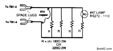
This dummy load was intended for tune-up of a 10-W CW ham rig. It should be useful for general-purpose applications in the HE range. The spade lugs shown can be replaced with a UHF connector for more versatility. The lamp acts as a relative power indicator. (View)
View full Circuit Diagram | Comments | Reading(696)
RF_SIGNAL_STRENGTH_INDICATOR
Published:2009/7/16 4:06:00 Author:Jessie


This circuit is useful for test purposes because it produces an output that varies logarithmically with RE input level. A Motorola MC3356 IC is used for its received signal strength output (pin 14), the other functions remain unused. An attenuator is placed at the input of the circuit to increase usable range. For best results, the circuit should be enclosed in a metal shielded box. (View)
View full Circuit Diagram | Comments | Reading(1017)
VIBRATION_DETECTOR
Published:2009/7/13 3:53:00 Author:May

A D'Arsonval meter movement is used as a vibration detector in this novel application. The meter acts as a generator, producing a voltage when the needle moves. An inexpensive panel meter can be used, but a high-sensitivity movement (50 μA) works best. (View)
View full Circuit Diagram | Comments | Reading(0)
ODD_EVEN_LOGIC
Published:2009/7/16 4:06:00 Author:Jessie

Accepts lye binary inputs and produces signal at either of two outputs according to whether sum of inputs is even or odd. Schmitt trigger is used between tunnel diodes and load to boost output voltage to 9 v.-W. H. Ko, Unique Tunnel-Diode Circuit Performs Odd-and-Even Logic, Electronics, 35:42, p 61-62. (View)
View full Circuit Diagram | Comments | Reading(926)
800_MHz_ANTENNA
Published:2009/7/13 3:53:00 Author:May

This simple quarter-wave antenna can improve performance on the 800-MHz band and can be built in just a couple of hours. (View)
View full Circuit Diagram | Comments | Reading(689)
TRANSISTOR_COUPLED_NAND_NOR_GATE
Published:2009/7/16 4:05:00 Author:Jessie
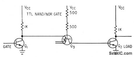
Coupling transistor Q3 feeds its base current into base of inverting transistor Q2 when gate Q1 is cut off. When Q1 is saturated, coupling transistor Q3 clamps base of Q2 to low voltage. Logic swing of 0.4 v occurs at high speed.-A. E. Skoures, Choosing Logic for Microelectronics, Electronics, 36:40, p 23-26. (View)
View full Circuit Diagram | Comments | Reading(616)
| Pages:710/2234 At 20701702703704705706707708709710711712713714715716717718719720Under 20 |
Circuit Categories
power supply circuit
Amplifier Circuit
Basic Circuit
LED and Light Circuit
Sensor Circuit
Signal Processing
Electrical Equipment Circuit
Control Circuit
Remote Control Circuit
A/D-D/A Converter Circuit
Audio Circuit
Measuring and Test Circuit
Communication Circuit
Computer-Related Circuit
555 Circuit
Automotive Circuit
Repairing Circuit