
Circuit Diagram
Index 707
SELF_STARTING_COUNTER
Published:2009/7/13 4:09:00 Author:May

Addition of three Iogic elements eliminates need for separate starting switch when using National MM5736 calculator chip as counter driving LED display. When reset switch is returned to normal posi-tion after pushing it to clear calculator, addi-tional parts serve to generate delayed pulse that gates digit output 2 into calculator and thus enters a 1. This action resets counter with single manual operation. -M. Watts, Calculator Chip Makes a Counter, National Semiconductor, Santa Clara, CA, 1974, AN-112, p 4. (View)
View full Circuit Diagram | Comments | Reading(1340)
MAXIMUM_ACCELERATION_RECORDING_CIRCUIT
Published:2009/7/16 4:27:00 Author:Jessie

The circuit (see figure) includes three 9 V batteries,one of which supplies the 9 V needed by the circuit,and all of which supply the 27V needed by the accelerometer Power is supplied to the accelerometer through field-effect diode D1,which regulates the accelerometer current to keep it In the range of 2 to 4mA. The accelerometer puts out an ac signal that peaks at a full-scale value of 5V when the ac component of acceleration reaches 50g(where g denotes normal Earth gravitation)The acceleration signal is coupled through C1 and D2 into C2,which retains the peak value for a short time The signal is fed through potentiometer R1 to the input terminal(pin 5) of a 10-level display driver,LM3914,that has equally spaced levels,each representing 5g, or of a similar circuit,LM3915,that has logarithmically spaced levels,with each succeeding level representing division of the next higher level by a factor of √2 (3 dB/step) Depending on the level of the input signal,the display driver energizes one of its ten output lines,each of which IS connected to one of ten 2-mA transparent-cap microfuses plugged into a module,If the fuse on a lineis still intact,then when that line is energized,the driver delivers a current of 10 mA, blowing the fuse The fuses can be inspected visually or electrically at any convenient time thereafter to determine which (if any) has blown、thereby determining what level of acceleration was reached. (View)
View full Circuit Diagram | Comments | Reading(1008)
FLUORESCENT_LAMP_DIMMER
Published:2009/7/13 4:09:00 Author:May

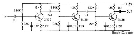
Tandem circuit with amplifier stages requires only 0.4 ma at 8V to drive 15-w fluorescent lamp at rated 300 ma while providing range of about 200 to 1 in luminance control. Conventional pho toflash trigger gives reliable starting for Lamp currents down to 1 ma.-L. L. Blackmer and A. T. Wright, Tandem-Transistor Circuit Regulates Fluorescent lamp,Electronics, 34:17, p114-116. (View)
View full Circuit Diagram | Comments | Reading(0)
CORE_FLUX_INTEGRATOR
Published:2009/7/16 4:26:00 Author:Jessie

Speeds grading and matching of magnetic cores. Miller integrator measures instantaneous and peak flux in cores at 60, 400, and 1,600 cps. Design approaches ideal response throughout 480-kc bandwidth and provides dosed-loop gain of 2 at fundamental excitation frequencies.-C. E. Goodell, Integrator-Amplifier for Core Measurements, Electronics, 31;7, p 110-113. (View)
View full Circuit Diagram | Comments | Reading(575)
SCR_BATTERY_CHARGING_REGULATOR
Published:2009/7/16 4:25:00 Author:Jessie

Can charge 12-v battery at up to 6-amp rate.When battery voltage reaches charged level, charging scr shuts off, and trickle charge determined by R4 flows.- Silicon Controlled Rectifier Manual, Third Edition, General Electric Co., 1964, p 109. (View)
View full Circuit Diagram | Comments | Reading(2514)
VOLUME_UNIT_DISPLAY_AND_ALARM
Published:2009/7/13 4:09:00 Author:May

This circuit uses two audio amplifiers, one for a microphone and one for a stereo input, to drive an LED bar-graph display, rather than a meter. When the input exceeds a certain level, an LED (#8 in this circuit) will light and also cause an alarm buzzer or some other signal to actuate. A switch is provided for source selection. (View)
View full Circuit Diagram | Comments | Reading(1219)
PROPORTIONAL_AMPLIFIER_FOR_INTEGRAT
Published:2009/7/16 4:25:00 Author:Jessie

ING CONTROL-Dual balanced feedback and form of bootstrapping give highly stable output of 35 V into 3,500 ohms, with voltage gain adjustable from 0 to 30 while output transformer return is to ground rather than B+.-C. H. Smoot and F. J. Karlov, Boiler Controller Simple Controller for a Complex Job, Electronics, 37:18, p 88-93. (View)
View full Circuit Diagram | Comments | Reading(838)
REED_SWITCH_CONTROLS_OPERATIONAL_AMPLIFIER
Published:2009/7/16 4:24:00 Author:Jessie


Circuit can gate out unwanted signals, maintain integrated output at specified level, or operate as synchronous detector. Maximum switching speed is 300 kc. Opening and closing S1 in synchronism with ac input signal allows synchronous detection and integration of signal. Amplifier integrates only portion of signal present while switch is open.-H. Penfield, Glass Reed Switch Controls Operational Amplifier, Electronics, 39:17, p 97-98. (View)
View full Circuit Diagram | Comments | Reading(1169)
HIGH_INTENSITY_LED_CIRCUIT
Published:2009/7/13 4:08:00 Author:May

The forward voltage for high-intensity LEDs (1.5 to 2.5 V) is too large for operation with one-cell batteries. The circuit shown overcomes this limitation with a boost-regulator technique-it drives controlled current pulses through the LED, regardless of the LED's forward voltage, and operates on input voltages from 6.2 V to below 1 V. The circuit is useful for bicycle lights, beacons, alarms, flashlights, and low-power indicators. IC1 is normally part of a regulated boost converter, but, in this case, it simply transfers energy without regulating the output. Omission of the usual rectifier and output filter capacitor makes the circuit compact, as does the high switching frequency (about 175 kHz).Programming resistor R1 sets the LED intensity by setting a peak current for the inductor and LED.A 10-kΩ value for R1 sets the approximate peak at 75 mA, and the average LED current at about 26 mA. A shutdown command tums off the OUT terminal completely, even if cell voltage exceeds the LED's forward voltage, by turning off the diode internal to IC1. (During shutdown, most step-up converters exhibit a troublesome dc path from the battery through the coil and diode to the load.) This circuit draws about 8 μA during shutdown and about 60 mA during normal operation. It operates for 35 hours continuously on one AA (or R4 size) alkaline cell. (View)
View full Circuit Diagram | Comments | Reading(1057)
CHARGER_CONTROL_WITH_REGULATED_D_C_REFERENCE
Published:2009/7/16 4:24:00 Author:Jessie

Eliminates need for separate reference battery. Control fires thyratron to pull in or out and initiate charging cycle when battery voltage drops.-V. Zeluff and J. Markus, Electronics Manual for Radio Engineers, McGraw-Hill, N.Y., 1949, p 545. (View)
View full Circuit Diagram | Comments | Reading(704)
100_DB_AMPLIFIER
Published:2009/7/13 4:08:00 Author:May
Used in distortion monitor to drive indicating vtvm.-G. H. Smith, Distortion Monitor Checks Linear Amplifier Characteristics, Electronics, 34:27, p 57-59.
(View)
View full Circuit Diagram | Comments | Reading(633)
CONSTANT_CURRENT_BATTERY_CHARGER
Published:2009/7/16 4:23:00 Author:Jessie

Thyratron-controlled motor drives phasing control rheostat to give fully automatic charging of 50 2-v storage cells at constant role of 2 amp.-J. Markus and V. Zeluff, Handbook of Industrial Electronic Control Circuits, McGraw-Hill, N.Y., 1956, p 150. (View)
View full Circuit Diagram | Comments | Reading(1573)
12_GHz_DECADE_COUNTER
Published:2009/7/13 4:08:00 Author:May


Motorola MC1696 BCD-output counter provides direct counting of events at up to 1.2 GHz without prescaling. Connection shown is for AC coupling of input signals. Decoupling capacitors are used on power supplies and all unused pins.MC1696 provides division by 10, with output driving cascaded MC10138 biquinary counters and associated latches connected to drive five-decade display as covered in report.-J, Roy, Event Counter and Storage Latches for High-Frequency, High-Resolution Counters, Moto-rola. Phoenix, AZ, 1975, EB-47.
(View)
View full Circuit Diagram | Comments | Reading(1046)
WELDER_BATIERY_CHARGER
Published:2009/7/16 4:22:00 Author:Jessie

During overnight charging of battery used to maintain equal-amplitude output current pulses for welder, circuit senses whether battery voltage is above or below required value for load current of 1 amp. If low, one-shot timer is actuated, to charge battery for preset interval. Voltage is then measured again, and charging repeated if necessary. If voltage is too high, load remains on until battery voltage drops to point where charger is actuated again.-F. T. Marcellino and A. A. Dargis, Circuit Keeps Voltage Constant for Welder Battery, Electronics, 38:21, p 88. (View)
View full Circuit Diagram | Comments | Reading(2244)
PREFERRED_EMITTER_FOLLOWER
Published:2009/7/13 4:07:00 Author:May
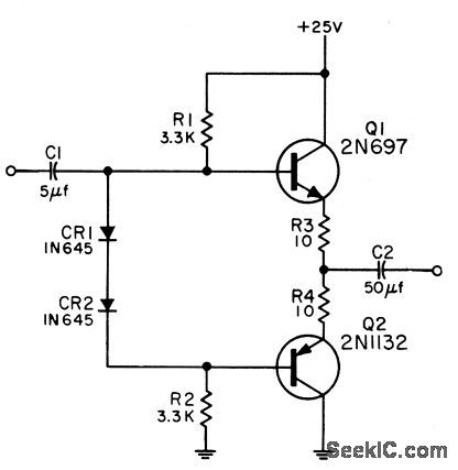
Used fo match high-impedance drcuit to low-impedance load. Will accept positive and negative pulses or sinusoidal input. Low output impedance for pulses resuhs in high operating speed into capadtive loads. Bandwidth for 600-ohm source impedonce is 50 cps to 3.5 iAc. Vohctge amplification is 0.8 ond power gain is 12 db.-NBS, Handbook Preferred Circuits Ncvy Aeronautical Electronic Equipment, Vol. II, Semiconductor Device Circuils, 1962, PSC 22 (originally PC 222), p 22-2. (View)
View full Circuit Diagram | Comments | Reading(833)
UNSYMMETRICAL_PULSE_GENERATOR
Published:2009/7/16 4:22:00 Author:Jessie

2N490 unijunction transistor serves as timer and trigger for flip-lop Q1-Q2 to provide 750-millisec rectangular pulses spaced 250 millisec apart, for energizing falling-sphere ac-celerometen.-C. H. Price, Jr., High-Current Solid-State Switches, Electronics, 33:38, p 72-73. (View)
View full Circuit Diagram | Comments | Reading(676)
BCD_THUMBWHEEL_SET_99_min_TIMER
Published:2009/7/13 4:07:00 Author:May

Provides timing in seconds to 99 s, and timing in minutes to 99 min, with 2-digit LED indicator showing elapsed time. Desired interval is set with BCD thumbwheel switches. LED readout counts up to preset time, then resets automatically to zero. Switch giving choice of seconds or minutes has center-off position that stops count temporarily for buming in portion of negative. Article gives construction details.-M.I.Leavey, Build a Unique Timer, 73 Magazine, Aug. 1977, p 66-71. (View)
View full Circuit Diagram | Comments | Reading(860)
HIGH_INPUT_Z_FET_AMPLIFIER
Published:2009/7/13 4:06:00 Author:May

Bias current is obtained from common-base current gen ercttor Q2. Q3 and Q4 function as complementary current multiplier. Bootstrapping for RB is obtained directly from emitter of Q3.Voltage gain is 2 and input impedance is 200 meg. Response is flat within 3 db from 1 to 500 kc with generator resistance of 1 meg.-Texas Instruments Inc., Solid-State Communications, McGraw-Hill,N.Y., 1966, p 187. (View)
View full Circuit Diagram | Comments | Reading(826)
FOUR_LED_BCD_DISPLAY
Published:2009/7/13 4:06:00 Author:May

Square-wave input pulses are counted by 7490 IC that drives LEDs indicating count in binary format up to 10 and then recycling Can be used for classroom demonstrations of counters,flip-flop action, and binary counting,Pulses can be obtained from UJT clock circuit operating at audio rate.-F M Mims, Computer Circuits for Experimenters, Radio Shack, Fort Worth, TX, 1974, p 85-93 (View)
View full Circuit Diagram | Comments | Reading(3398)
FLUORESCENT_LAMP_DIMMER
Published:2009/7/13 4:05:00 Author:May

Conventional photoflash trigger circuit R-C-T2 gives reliable starting for lamp currents down to 1 ma. High-voltage trigger pulse is applied to foil strip or wire loop going around lamp.Transistor can be 2N1047, with resistance values chosen to provide required d-c operating voltages.-L. L. Blackmer and A. T. Wright, Tandem.Transistor Circuit Regulates Fluorescent lamp, Electronics, 34:17, p114-116. (View)
View full Circuit Diagram | Comments | Reading(1313)
| Pages:707/2234 At 20701702703704705706707708709710711712713714715716717718719720Under 20 |
Circuit Categories
power supply circuit
Amplifier Circuit
Basic Circuit
LED and Light Circuit
Sensor Circuit
Signal Processing
Electrical Equipment Circuit
Control Circuit
Remote Control Circuit
A/D-D/A Converter Circuit
Audio Circuit
Measuring and Test Circuit
Communication Circuit
Computer-Related Circuit
555 Circuit
Automotive Circuit
Repairing Circuit