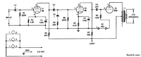
Amplifier Circuit
SINGLE_ENDED_HI_Fl_AMPLIFIER
Published:2009/7/13 3:04:00 Author:May | From:SeekIC

The circuit as shown will handle up to about 0.5 V; above that, distortion will be present. The input stage amplifies the signal voltage about seven times, and the second stage amplifies the voltage about 10 times. Both stages use type 56 triodes (V1 and V2). The output stage uses a type 2A3 tube, V3. Two 22.5-V batteries wired in series (B1) were used to provide 45 V on the grid of V3. In this circuit (and other single-ended amplifiers), direct current flows in the primary of the output transformer (T1) to use the circuit modification shown in Fig. 2. That change keeps dc out of the primary at some sacrifice in power. With the modification, the amplifier will be flat (within 1 dB) from 20 to 20,000 Hz. (The modified circuit requires that a high-voltage transformer be used in the power-supply circuit.) Note that transformer T1 is shown connected from one end of the primary to the center tap. That was done because it is assumed that the transformer used will have a primary impedance of about 8000 Ω. The recommended load for a 2A3 tube (V3) is 2500 Ω for maximum output, but increasing the impedance lowers the distortion while only slightly lowering the power.
Reprinted Url Of This Article:
http://www.seekic.com/circuit_diagram/Amplifier_Circuit/SINGLE_ENDED_HI_Fl_AMPLIFIER.html
Print this Page | Comments | Reading(3)

Article Categories
power supply circuit
Amplifier Circuit
Basic Circuit
LED and Light Circuit
Sensor Circuit
Signal Processing
Electrical Equipment Circuit
Control Circuit
Remote Control Circuit
A/D-D/A Converter Circuit
Audio Circuit
Measuring and Test Circuit
Communication Circuit
Computer-Related Circuit
555 Circuit
Automotive Circuit
Repairing Circuit
Code: