
Circuit Diagram
Index 689
INFRARED_ANALYZER
Published:2009/7/16 3:10:00 Author:Jessie

Circuit shows phase-sensitive demodulator, 13-cps amplifier, and modulator of servo system used in Perkin-Elmer Tri-Non triple-beam analyzer for measuring amount of infrared energy absorbed by component of interest in flowing sample of industrial process stream. Servo motor tums variable null-path attenuator to cancel radiation unbalance and restore null-G. C. Carroll, lndustrial Instrument Servicing Hand-book, McGraw-Hill, N.Y., 1960, p 8-51. (View)
View full Circuit Diagram | Comments | Reading(929)
AUTOMATIC_IGNITION_ADVANCE
Published:2009/7/16 3:08:00 Author:Jessie
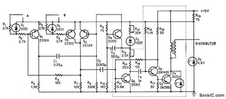
Inductive pickups on engine crankshaft feed to A and B, to make fining vary with engine speed by triggering monostable delay placed ahead of basic Delcotronic spark generator (dashed lines).-A. R. Hayes, Electronically Controlling Auto's Engine Spark,Electronics, 37:32, 43-44. (View)
View full Circuit Diagram | Comments | Reading(1108)
AUTO_TACHOMETER
Published:2009/7/16 3:06:00 Author:Jessie
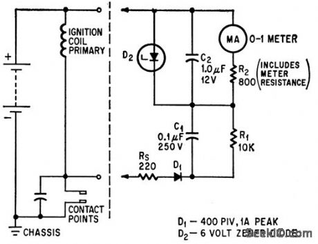
Connects to automobile circuit at battery and at distributor contact points.Zener diode D2 limits maximum charging voltage across C2.-J. A. Irvine, No Moving Parts in Auto Tachometer, Electronics, 39:9, p 77-78. (View)
View full Circuit Diagram | Comments | Reading(961)
AUDIBLE_TURN_SIGNAL_INDICATOR
Published:2009/7/16 3:05:00 Author:Jessie
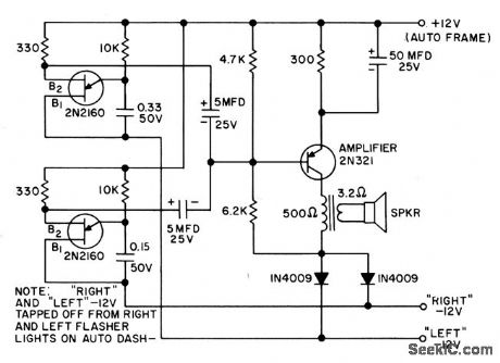
Produces two different tones in synchronism with turn-signal flashers. Diodes prevent short-circuit. For autos with positive ground. - Transistor Manual, Seventh Edition, General Electric Co., 1964, p 381. (View)
View full Circuit Diagram | Comments | Reading(862)
DC_AMMETER_II
Published:2009/7/16 3:03:00 Author:Jessie
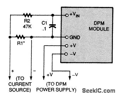
As shown here, a DPM module can be used as a dc ammeter.
R1 is chosen to provide a voltage drop so that the meter reads full scale at the maximum desired current reading. This drop should be kept as small as possible. Typically, it will be 100 to 200 mV dc. (View)
View full Circuit Diagram | Comments | Reading(952)
BOLOMETER_AMPLIFIER_AND_DETECTOR
Published:2009/7/16 3:01:00 Author:Jessie

Used in infrared horizon sensor of meteorological satellite. Zener diode D1 provides low-impedance constant-voltage source of bias for detector.-F. Schwarz and W. Chou, Tiros Weather Satellites, Eleatronics, 34:39, p 136-137. (View)
View full Circuit Diagram | Comments | Reading(742)
DC_AMMETER_I
Published:2009/7/16 3:01:00 Author:Jessie
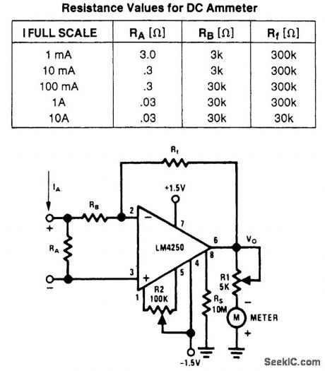
For dc readings higher than 100μA, the inverting amplifier configuration shown in the figure provides the required gain. Resistor RA develops a voltage drop in response to input current IA, This voltage is amplified by a factor equal to the ratio of RF/RB, RB must be sufficiently larger than RA, so as not to load the input signal. The figure also shows the proper values of RA, RB, and Rf for full-scale Deter deflections from 1 mA to 10 A. (View)
View full Circuit Diagram | Comments | Reading(1078)
LOGARITHMIC_THIN_FILM_I_F_AMPLIFIER
Published:2009/7/16 3:00:00 Author:Jessie

Un-tuned stages eliminate need for inductors in 60-Mc log i-f module while giving gain of 10 db,-R.Leslie and Townsend, Inductors No Problem: New Thin-Film Amplifier, Electionics,36:23, p 46-49. (View)
View full Circuit Diagram | Comments | Reading(545)
DOUBLE_GATED_AGC
Published:2009/7/16 3:00:00 Author:Jessie

Uses zener diode to supply standing bias for agc bus. -W. A Rheinfelder, Designing Automatic Gain Control Systems, EEE, 13;1, p 53-57. (View)
View full Circuit Diagram | Comments | Reading(508)
LOW_Q_22_MC_I_F_DESIGN
Published:2009/7/16 2:59:00 Author:Jessie
Article gives detailed design procedure, with example worked out for 480-kc bandwidth and gain of 92 db. For high-Q stage, 1.1 K load resistor is changed to 12K.-J. F. Klarl, A Systematic Approach For Designing IF Amplifiers, EEE, 12:3, p 40-44. (View)
View full Circuit Diagram | Comments | Reading(641)
DIODE_T_ATIENUATOR_AGC
Published:2009/7/16 2:59:00 Author:Jessie

All three diodes are simultaneously controlled, to give excellent agc action over control range of 20 db, although insertion loss is high. Frequency response is excellent up to 150-Mc cutoff.-W.A. Rheinfelder, Designing Automatic Gain Control Systems, EEE, 13:1, p 53-57. (View)
View full Circuit Diagram | Comments | Reading(558)
SINGLE_TRANSISTOR_I_F_AMPUFIER
Published:2009/7/16 2:59:00 Author:Jessie
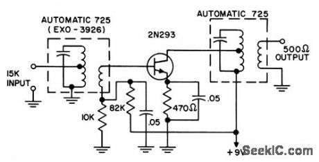
Designed for broadcast-band transistor radio. Neutralization is unnecessary with 2N293 rate-grown npn transistor used.-Transistor Manual, Seventh Edition, General Electric co.,1964, p 285. (View)
View full Circuit Diagram | Comments | Reading(716)
PREFERRED_DISTANCE_MARK_GENERATOR
Published:2009/7/16 2:59:00 Author:Jessie

Produces train of accurately spaced pulses. Number of pulses in train is determined by duration of input gate, and distance mark spacing is controlled by values of L1, C2, and R3. R13 is 250 ohms maximum. Output is 0 to 50 v positive, for distance mark spacings of 0.5 to 25 miles in search radar V2 is switched Hartley oscillator, whose output is shaped by mvbr shaper V3-V4, for triggering blocking oscillator VS to produce narrow marker pulses.-NBS, Handbook Preferred Circuits Navy Aeronautical Electronic Equipment, Vol I, Electron Tube Circuits, 1963, PC 55, p 55-2. (View)
View full Circuit Diagram | Comments | Reading(467)
60_MC_I_F_WITH_2N743
Published:2009/7/16 2:58:00 Author:Jessie
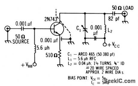
Silicon epitaxial transistor has unconditional stability at this frequency, simplifying alignment. Gains up to 16 db per stage are possible with conjugate match at output. Noise figure is good.-Texas Instruments Inc., Solid-State Communications, McGraw-Hill, N.Y., 1966, p 311. (View)
View full Circuit Diagram | Comments | Reading(910)
NINE_FIXED_GAIN_STAGES_GIVE_AGC
Published:2009/7/16 2:58:00 Author:Jessie

Monopulse radar amplifier stages are used in cascade, each with different fixed gain and a slicer that switches from that gain to unity gain if signal exceeds predetermined reference level. Give gain up to 80 db in 0.5-db steps, equivalent to fast agc, to give constant 10-v output for signals ranging from 1 mv to 10 mv. -W. W. Smith, Fast AGC Amplifier Locks Monopulse Radar on Target, Electronics, 36:39, p 34-36. (View)
View full Circuit Diagram | Comments | Reading(594)
MOBILE_I_F
Published:2009/7/16 2:58:00 Author:Jessie
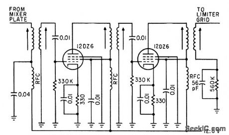
Two 455-kc i-f stages provide gain of 20 per stage and average band-width of 12 kc.-C. Gonzalez and R. J. Nelson, Design of Mobile Receivers with Low-Plate-Potential Tubes, Electronics, 33:34, p62-65. (View)
View full Circuit Diagram | Comments | Reading(593)
30_NSEC_5000_V_30_AMP_PULSES
Published:2009/7/16 2:57:00 Author:Jessie

Used for testing magnetic materials at narrow pulse widths. Four hard tubes in parallel drive test cores with 0.1 megawatt peak power and give some degree of regulation during pulsing.-G. A. Reeser, How Magnetic Materials Behave at Nanosecond Pulse Widths, Electronics, 34:36, p 72-75. (View)
View full Circuit Diagram | Comments | Reading(582)
SIMPLE_AGC
Published:2009/7/16 2:57:00 Author:Jessie

Used to keep output of communication receiver relatively constant with varying input signals.-NBS, Handbook Preferred Circuits Navy Aeronautical Electronic Equipment, Vol. 1, Electron Tube Circuits, 1963, p N 12-4. (View)
View full Circuit Diagram | Comments | Reading(830)
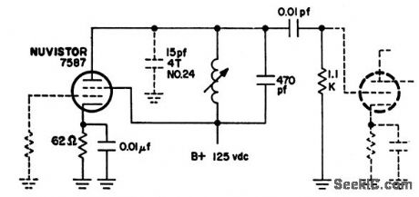
88_108_MC_F_M_CONVERTER_WITH_AFC
Published:2009/7/13 6:45:00 Author:May

Variable-capacitance diode provides frequency control of tunnel-diode oscillator.- Transistor Manual. Seventh Edition,General Electric Co.1964,P361. (View)
View full Circuit Diagram | Comments | Reading(752)
D_C_TO_AUDIO_FREQUENCY_CONVERTER
Published:2009/7/13 6:39:00 Author:May

Response is nonlinear;1.7V input voltage gives 100 cps;1.9V gives 200 cps; 2.25V gives 400 cps;10V gives 2,000 cps.Output waveform approximates rectangular shape.-D.Busby,Jr.DC to frequency Converter,EEE,10:11,P31. (View)
View full Circuit Diagram | Comments | Reading(568)
| Pages:689/2234 At 20681682683684685686687688689690691692693694695696697698699700Under 20 |
Circuit Categories
power supply circuit
Amplifier Circuit
Basic Circuit
LED and Light Circuit
Sensor Circuit
Signal Processing
Electrical Equipment Circuit
Control Circuit
Remote Control Circuit
A/D-D/A Converter Circuit
Audio Circuit
Measuring and Test Circuit
Communication Circuit
Computer-Related Circuit
555 Circuit
Automotive Circuit
Repairing Circuit