
Circuit Diagram
Index 687
NOVELTY_LED_FLASHER
Published:2009/7/13 11:16:00 Author:May

The circuit contains three oscillators, one based on a 555 (IC1) and the others centered around a 556 (IC2). When S1 is on, each oscillator's LED (LED1, LED2, or LED3) will flash rhythmically, according to the setting of its potentiometer (R1, R2, or R3), and the capacitor selected by its switch (S2, S3, or S4). Each oscillator output is capable of driving up to 20 jumbo LEDs con-nected in parallel. Arrange the LEDs to suit your taste. The circuit will operate on a battery or any 9- to 12-Vdc source. (View)
View full Circuit Diagram | Comments | Reading(1759)
TACHOMETER_AMPLIFIER
Published:2009/7/16 3:32:00 Author:Jessie
Unijunction transistor is basis of simple, inexpensive tachometer amplifier or frequency meter. Each negative input pulse of sufficient amplitude triggers ujt, so capacitor is discharged through ujt. Capacitor is then recharged through d-c am meter by current having sawtooth waveform that minimizes flutter at low frequencies.-T. P. Sylvan, Frequency Meter-Tachometer Amplifier, EEE, 10:8, p 25-26. (View)
View full Circuit Diagram | Comments | Reading(914)
XENON_FLASHTUBE_CIRCUIT
Published:2009/7/13 11:14:00 Author:May

These are basic circuits for firing Xenon flashtubes. Which circuit is applicable depends on trigger coil polarity. (View)
View full Circuit Diagram | Comments | Reading(948)
ZERO_POWER_ENGINE_TACHOMETER
Published:2009/7/16 3:22:00 Author:Jessie
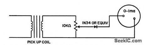
Requires no battery or other power source. Coil from 10 K relay serves as pickup for mounting near rotating magnets of flywheel of outboard motor or magneto. When rotating magnets are not available, as in most automotive engines, variable-reluctance pickup is used. This can be mode from old loudspeaker, mounted so fan blades of generator pass between pickup coil and permanent magnet. Coil mounting should be aluminum to maintain calibration that is made with commercial tachometer.-K. M. Bronscome, Engine Tachometer, EEE, 10:9,p 27. (View)
View full Circuit Diagram | Comments | Reading(625)
AC_LIGHT_FLASHER
Published:2009/7/13 11:12:00 Author:May

This circuit uses a 555 timer that is configured in an unusual way in that trigger pin 2 is activated by the voltage from a photocell to sense when the lamp is lit. The relay time constants affect the flash rate. (View)
View full Circuit Diagram | Comments | Reading(993)
MULTIPLE_FEEDBAGK_BANDPASS_ACTIVE_FILTER
Published:2009/7/13 11:05:00 Author:May

This is a multiple-feedback-path(MFP)bandpass filter. (View)
View full Circuit Diagram | Comments | Reading(964)
TV_ON_INFRARED_BEAM
Published:2009/7/16 3:22:00 Author:Jessie

Forward-biased gallium arsenide diode converts video input signal to video-modulated infrared radiation with up to 85% efficiency.-R. H. Rediker et al., Gallium-Arsenide Diode Sends Television by Infrared Beam, Electronics, 35:40, p 44-45. (View)
View full Circuit Diagram | Comments | Reading(596)
ACTIVE_HP_FILTER_
Published:2009/7/13 11:04:00 Author:May

Interchanging the resistors and capacitors transforms the normalized low-pass filter into a high-pass filter with the same corner frequency (a). Notice that the Sallen-Key filter must be modified according to impedance levels at each node. This yields a filter with equal-value capacitors and unequal-value resistors, an improvement over the traditional low-pass design of equal-value resistors and unequal-value capacitors. The graphs in (b) indicate that the normalized high-pass filter compares favorably with the Sallen-Key filter in high-pass applications. (View)
View full Circuit Diagram | Comments | Reading(757)
FREQUENCY_METER
Published:2009/7/16 3:22:00 Author:Jessie
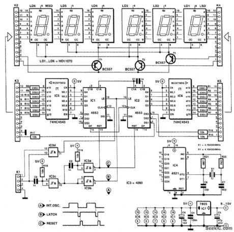
The counter makes use of two 3-digit DCD counters that have a multiplexed output with buffer memory and a RESET input. The multiplexed output signal is converted by an integrated BCD-to-seven-segment converter and then applied to an LED display. The necessary clock signal is generated by a crystal of 4.194304 MHz and a counter that divides the signal by 223. The result is a stable digital signal with a frequency of 0.5 Hz. The time during which the clock signal is high, and measurements can occur, is exactly 1 s. Owing to this arrangement, a new measuring value is displayed every 2 s. If the meter is used to measure frequency, the internal clock signal at pin 3 of K1 must be linked to pin 2 of K1. Gate IC3d then operates as a lock; every time the clock is high, the measurand at pin 1 of K1 is applied to the clock input of IC1. This circuit is connected in series with IC2 to form a six-digit counter. At the end of the measurement, a latch pulse is generated at the output of IC3c with the aid of R19 and C3. After this signal has been inverted in IC3b, it is applied to the LATCH in-put of IC1 and IC2. At the command of this signal, the current counter state is stored in the buffer memory. At the end of the LATCH pulse, network R18-C2-IC3a generates a RESET pulse with which the counter is reset. In the circuit as shown, the counter can be used for signals with frequencies from 1 Hz to 1 MHz. If higher frequencies are envisaged, the measurement time must be adapted accordingly. There are limits to this, though: With a supply voltage of 5V, the 4553 can be used for frequencies up to 1.5 MHz; with 7V, up to 5 MHz; and with 15V, up to 7 MHz. Still higher frequencies require the use of a prescaler. The current drawn by the circuit (as shown) does not exceed 50 mA, which makes a battery supply feasible. (View)
View full Circuit Diagram | Comments | Reading(0)
CERAMIC_FILTER_INTERFACING
Published:2009/7/13 11:01:00 Author:May

Ceramic or mechanical filters can provide a frequency-selective output. (View)
View full Circuit Diagram | Comments | Reading(583)
PASSIVE_LONGWAVE
Published:2009/7/16 3:22:00 Author:Jessie
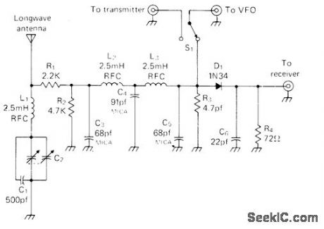
Uses VFO of amateur-band transmitter to supply heterodyne for bringing in frequencies below 450-kHz broad-cast band on amateur receiver, such as Omega navigation station on 10.2-13.6 kHz, NAA Teletype on 17.8 kHz, and GBR time signals on 16 kHz. L1-C1-C2 100.kHz input wavetrap for loran C can be omitted at far-inland locations. C2 is two-gang broadcast variable capacitor with both sections in parallel. Mount L2 at right angle to L3. Converter should be well shielded. Operation involves tuning receiver to bottom of any amateur radio band, on frequency equal to difference between VFO and that to which receiver is tuned. If VFO is on 7 MHz and receiver is tuned to 7.085 MHz, combination will be set for 85-kHz station. In USA, unlicensed transmission on 160-190 kHz is permitted with 1-W input and 50-foot antenna including length of transmission line. -M. Muench, Longwave Simplified, CQ, March 1976, p 41-42. (View)
View full Circuit Diagram | Comments | Reading(1728)
LOW_PASS_FILTER_PHASE_CORRECTOR
Published:2009/7/13 11:00:00 Author:May

In some applications, it might be desired, or even be essential, that the bandwidth of the audio signal be limited, but that the phase relationship with the original signal be retained. A surroundsound encoder is a good example of this. The requirement can be met by combining the low-pass filter with an all-pass section and having the filtered signal compared with the signal corrected by the all-pass network. As it happens, the phase transfer of a first-order all-pass filter is exactly the same as that of a second-order critically damped network. The design of such a combination is shown in Figure 1. In this, the all-pass network is based on IC1a and the low-pass section on IC1b. The -6-dB cutoff point is at exactly 1 kHz, and the -3-dB rolloff is at 642 Hz. (View)
View full Circuit Diagram | Comments | Reading(1021)
600_TO_3000_Hz_TUNABLE_NOTCH_FILTER_CIRCUIT
Published:2009/7/13 10:54:00 Author:May

This figure shows a notch filter that will tune roughly from 600 Hz to 3 kHz; it has been used by ham and SWL builders for a number of years. It is used for notching out unwanted CW stations or for notching out heterodynes in receivqr outputs. Insert this filter between the headphone output of the receiver and a power amplifier stage. (View)
View full Circuit Diagram | Comments | Reading(768)
PASSIVE_TACHOMETER
Published:2009/7/16 3:21:00 Author:Jessie
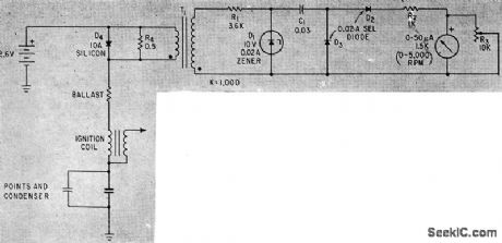
Circuit is placed in series with ignition coil to pick up ignition pulses and feed them to integrating rate-meter calibrated in rpm. Number of pulses per shaft revolution depends on number of cylinders.-F.Trainor, Unique Engine Tachometer uses only Passive Components, Electronics, 35:30. P 40-41. (View)
View full Circuit Diagram | Comments | Reading(600)
SUBSONIC_FILTER
Published:2009/7/13 10:52:00 Author:May

This filter is a fifth-order high-pass section that provides 1 dB attenuation at 20 Hz. Below that, however, the response drops off very steeply; the -3-dB point is at 17.3 Hz, and at 13.6 Hz, the attenuation is 10 dB. Note that it is important that C1 to C5 are within 1 percent of one another. Their individual tolerance is not so important because that merely affects the cutoff point. However, mutual deviation adversely affects the shape of the response, which should be a Butterworth characteristic as specified. All resistors are 1-percent types. (View)
View full Circuit Diagram | Comments | Reading(4411)
IF_BANDPASS_FILTER_SWITCH
Published:2009/7/13 10:31:00 Author:May

Selecting IF bandpass filters via series/shunt PIN-diode switching can be accomplished with this circuit. Diodes can be MV3404 or similar types. (View)
View full Circuit Diagram | Comments | Reading(734)
SIMPLE_SQUARE_WAVE_GENERATOR
Published:2009/7/16 3:19:00 Author:Jessie
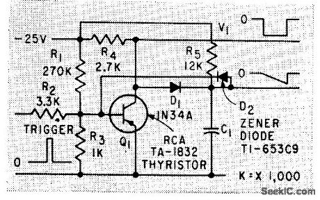
Circuit performance is mode independent of active elements by using transistor only as switch. For reliable operation, circuit requires extra 10% of output-pulse-width dead time between triggers.-C. A.. Von Urff and R. W. Ahrons, How to Generate Accurate Sawtooth and Pulse Waves, Electronics, 32:50, p 64-66. (View)
View full Circuit Diagram | Comments | Reading(1101)
STAIRCASE_INTEGRATOR_FOR_ROTATION_ANALYZER
Published:2009/7/16 3:19:00 Author:Jessie
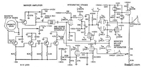
Used to observe relationship of crankshaft angle in gosoline engines to cylinder pressure and ignition timing. Parameters under study are indicated by angular displacement of rotating disk and are converted into signals for cro display. Magnetic drum is coupled to shaft under test. Ferrite-coated fiber disk with 1°magneticcdly recorded markers is source for pulses that are amplified for staircase integrating amplifier that feeds cro.-G. E. Edens, Stairstep Integrator Analyzes Rotation, Electronics, 31:13,p 41-43. (View)
View full Circuit Diagram | Comments | Reading(543)
100_200_kHz_TO_18_2_MHz
Published:2009/7/16 3:18:00 Author:Jessie
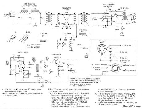
High-performance low-frequency converter picks up experimental CW, SSB, RTTY, and beacon signals in 160-190 kHz band for conversion to tunable IF range of modern communication receiver. Double-balanced diode-ring mixer has conversion loss of 6-8 dB and will stand up against strong signals without causing overloading and cross-modulation. Use 1N914 matched diodes. Diplexer at mixer output is tuned to 3 times converter IF. Article covers construction and alignment. -D. DeMaw, A High-Performance Low-Frequency Converter, QST, June 1977, p 23-26. (View)
View full Circuit Diagram | Comments | Reading(4165)
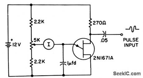
TUNNEL_DIODE_PULSE_GENERATOR
Published:2009/7/16 3:18:00 Author:Jessie

Negative-resistance characteristics of tunnel diode gives fast-rise-time rectangular pulses, in. dependently of signal frequency. Used here with common-base transistor amplifier-G. B. Smith, Tunnel Diode Generates Rectangular Pulses, Electronics, 33:48, p 124-125. (View)
View full Circuit Diagram | Comments | Reading(907)
| Pages:687/2234 At 20681682683684685686687688689690691692693694695696697698699700Under 20 |
Circuit Categories
power supply circuit
Amplifier Circuit
Basic Circuit
LED and Light Circuit
Sensor Circuit
Signal Processing
Electrical Equipment Circuit
Control Circuit
Remote Control Circuit
A/D-D/A Converter Circuit
Audio Circuit
Measuring and Test Circuit
Communication Circuit
Computer-Related Circuit
555 Circuit
Automotive Circuit
Repairing Circuit