
Circuit Diagram
Index 685
NEON_TRIODE_OFF_ON_GATE
Published:2009/7/16 1:50:00 Author:Jessie

Supply voltage is set midway between firing and extinction voltages of neon tube. Neon conducts when triggered by momentary increase in voltage, and continues conducting until supply voltage is momentarily lowered below extinction voltage. Can be used to produce Low-repetition-rote pulses. Triode may be 6AV6 or 1/2 12AXT.-R. L. Lves, Neon Triode Gives Low- Speed Gate, Electronics, 31:11, p 170-174. (View)
View full Circuit Diagram | Comments | Reading(536)
BUTTON_AND_BEAD_COUNTER
Published:2009/7/13 20:36:00 Author:May

Tiny objects passing before photodiode are counted by Schmitt trigger and four binary stages at up to 30 counts per second, with electromechanical counter readout.-E. J. Brach, Photocell Triggers Counting Circuit, Electronics,38:13,p74-75 (View)
View full Circuit Diagram | Comments | Reading(641)
27_MC_RECEIVER_FOR_TONE_MODULATED_DATA
Published:2009/7/13 20:35:00 Author:May

Two selective amplifiers, one tuned to 400 cps and other to 1,400 cps, drive relays K3 and K4 to control printing register for recording remote events such as passage of birds through infrared curtain.-P. A. love and J. Czekajewski, Infrared Curtain System Detects and Counts Moving Objects, Electron-ics, 34:31, p40-43. (View)
View full Circuit Diagram | Comments | Reading(549)
BASIC_BAR_GRAPH_DISPLAY_CIRCUIT
Published:2009/7/13 20:30:00 Author:May
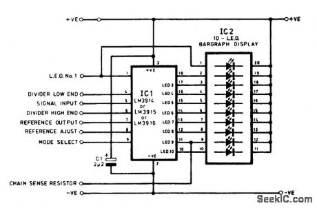
An LM3914 is shown connected to an LED bar-graph display. (View)
View full Circuit Diagram | Comments | Reading(2392)
VARYING_LCD_BIAS_CIRCUIT
Published:2009/7/13 20:29:00 Author:May
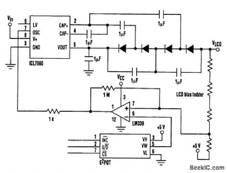
Large dot-matrix LCD drivers require a negative bias voltage of up to 24 V, depending on the LCD multiplex ratio One alternative is to combine the 7660 with a diode/capacitor voltage multiplier, using the 7660's internal square-wave generator as the signal source. This circuit will deliver an output of 37Vin-4Vf, thus generating approximately 24 V from a 9-V input. Additional stages could be added to the multiplier to allow 24 V to be generated from a 5-V regulated supply. In this circuit ,the output voltage is set by the input voltage, which might be inconvenient. If a variable voltage is required for contrast adjustment, Some form of microprocessor control over the output Voltage will be needed. One particular configuration used a Xicor E2POT to control the output by using a feedback circuit that pulls the oscillator pin of the 7660 low when the bias voltage exceeds the desired levels. This prevents further pumping of charge until the output returns to the required voltage The out-put ripple is set by the hysteresis resistor in the comparator circuit. (View)
View full Circuit Diagram | Comments | Reading(2012)
28_TO_420_V_D_C_CONVERTER
Published:2009/7/13 20:27:00 Author:May

Efficiency is 87%, power output 125w, output voltage ripple 0.7V p-p, and operating frequency 10 kc. Ambient temperature range is -50 to 125℃. Transformer winding data is given.- Transistor Manual, Seventh Edition, General Electric Co.1964, p238. (View)
View full Circuit Diagram | Comments | Reading(559)
ELECTROLUMINESCENT_PANEL_DRIVER
Published:2009/7/13 20:27:00 Author:May

Driving electroluminescent (EL) panels, such as those used for backlighting LCD screens in portable devices,is a challenge because they are capacitive loads and require high-voltage ac drive signals. Typically, EL panels exhibit about 3 nF/in2 capacitance. The LT1305 circuit shown can drive an EL panel with up to 100 nF total capacitance. The LT1305 micro power dc-to-dc converter contains an internal power switch capable of up to 2 A switch current. The high-power switch drives the primary of fly back transformer T1. A minimum input voltage of 1.8 V ensures operation with two-cell supplies. The input voltage is boosted to a voltage that ranges from 166 to 248 Vdc, as set by R1. The ac drive waveform is created by an external square-wave control signal turning on and off the NPN transistor, bringing point A to ground and inverting the voltage across the panel and then returning to a high positive voltage. By adjusting R1, the panel ac drive voltage can be set from 83 to 115 Vrms to alter the display brightness. The color or hue of the display can also be slightly varied by changing the frequency of the square-wave drive signal. This control signal can be from a system microprocessor output pin. (View)
View full Circuit Diagram | Comments | Reading(2307)
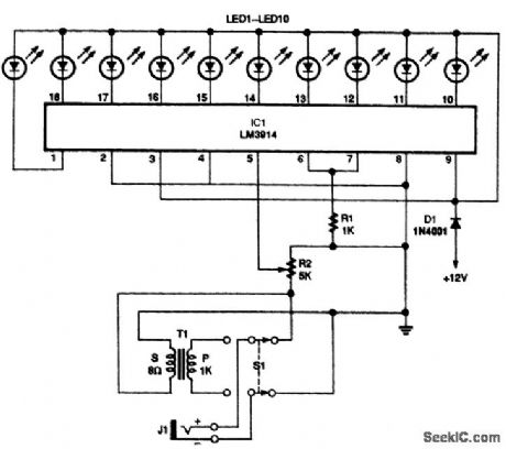
BAR_GRAPH_DISPLAY
Published:2009/7/13 20:26:00 Author:May
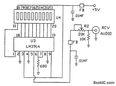
This bar-graph display monitors received audio level and can be useful for tuning, peaking, etc. (View)
View full Circuit Diagram | Comments | Reading(831)
TRICOLOR_LED_SIGN_DISPLAY
Published:2009/7/13 20:25:00 Author:May
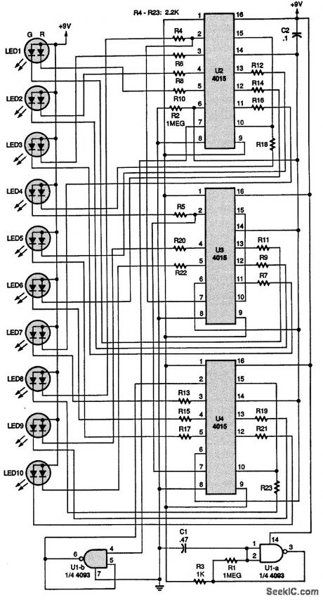
The purpose of this circuit is to light three-terminal LEDs in sequence on a small sign for a model railroad. Capacitor C2 is connected to the resets of the three 4015 shift registers, U2 to U4. When the circuit is first turned on, C2 automatically sets all the outputs to 0, thus inputting a 1 through U1-b, a section of a 4093 NAND Schmitt trigger, to the A input (pin 7) of U2. The circuit is clocked by U1-a, which is connected as an oscillator, and U1-a inverts the 0s to 1s until the first 1 is recirculated to the output of the last shift register, U4. Then the 1s become 0s and they recirculate. That all repeats as U1-a clocks the shift registers. When the first 1 is received at the first output of U2, the LED segment connected to it lights. As U1-a clocks the shift register, the LEDs connected to the other outputs sequentially light up red. After ten clock cycles, the clock skips two, and then continues lighting up the green segments of the LEDs, giving a yellowish-orange tint to them. After all the LEDs are lit, the shift register starts turning off the red LED segments. That leaves the green segments on-the third color from the LEDs. The oscillator continues to clock the green LEDs off, leaving the sign dark. After that cycle is completed, the operation repeats, giving the effect of a sign that goes from red to yellow to green to dark. (View)
View full Circuit Diagram | Comments | Reading(2392)
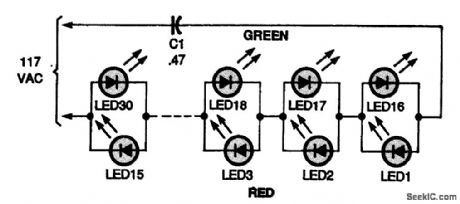
ALTERNATING_COLOR_LED_LIGHT_STRING
Published:2009/7/13 20:24:00 Author:May
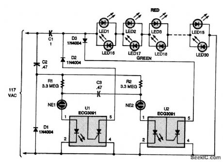


This circuit produces a string that alternates between red and green at a steady 1-s rate, making it an attractive addition to any holiday display. Two neon bulbs, NE1 and NE2, are connected in a relaxation-oscillator circuit that switches back and forth at about a 1-Hz rate. The values of R1, R2, and C3 set the switching rate. Dc power for the neon oscillator circuit is supplied via C2 and Dl. No dc filter capacitor is used or needed. When NE1 turns on, current flows through the LED in U1, an optocoupler, turning on the SCR and grounding the anode of D2. Only the positive half cycle of the ac waveform passes to the LEDs, which lights only the red ones (LED1 to LED15). After about 1 s, NE1 turns off and NE2 turns on, causing U2 to ground the cathode of D3. Now only the negative half cycle of the ac waveform passes to the LEDs, which lights only the green ones. If you'd like a change rate of less than 1 s, lower the values of R1 and R2 ; to lengthen the rate, increase the value of capacitor C3. (View)
View full Circuit Diagram | Comments | Reading(1075)
AUTODYNE_CONVERTER
Published:2009/7/13 20:23:00 Author:May

Single transistor stage serves as combination local oscillator, mixer, and i-f amplifier in transistor radio.Mixer operates in grounded-emitter configuration. I-f value is 455 kc.- Transistor Manual, Seventh Edition, General Electric Co.1964, p284. (View)
View full Circuit Diagram | Comments | Reading(1681)
LED_BAR_GRAPH_CIRCUIT
Published:2009/7/13 20:22:00 Author:May
This circuit uses an LM3914 with either dc or audio input. R2 controls the input level. The display can be either ten discrete LEDs or a bar-graph LED assembly. (View)
View full Circuit Diagram | Comments | Reading(2022)
CIVIL_AIR_PATROL_CONVERTER
Published:2009/7/13 20:22:00 Author:May

Tunnel-diode oscillator in self-oscillating converter permits reception on aviation band with auto radio.- Transistor Manual, Seventh Edition, General Electric Co.1964,p358. (View)
View full Circuit Diagram | Comments | Reading(671)
LED_DC_LEVEL_INDICATOR
Published:2009/7/13 20:21:00 Author:May
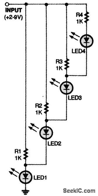
Here's a simple dc-level indicator (View)
View full Circuit Diagram | Comments | Reading(865)
LED_LIGHT_STRING
Published:2009/7/13 20:21:00 Author:May
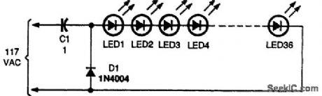
Capacitor C1, a 1-μF, 400-V Mylar or similar unit, operates in the circuit as a no-loss, ac-limiting component connected in series with the LED string. The capacitor's reactance acts like a transistor to the ac without the losses found with a standard power resistor. The 1N4004 silicon diode protects the LEDs from reverse-voltage damage. The circuit was tested with 36 red and green LEDs with an operating current of about 15 mA. Additional LEDs might be added in series if you wish, but that will reduce the brilliance of the LED string somewhat. (View)
View full Circuit Diagram | Comments | Reading(1406)
ELECTROLUMINESCENT_PANEL
Published:2009/7/13 20:20:00 Author:May

Electroluminescent (EL) panels offer a viable alternative to LED, incandescent, or CCFL backlighting systems in many portable devices. EL panels are thin, rugged, lightweight, and low power; require no diffuser, and emit aesthetically pleasing blue-green light. Capacitive in nature, they typically exhibit about 3000 pF/in2 of panel area and require a low-frequency (50 Hz to 1 kHz) 120-V rms ac drive. These problems can be solved by using a setup that includes an LT1303 micropower switching-regulator IC along with a small surface-mount transformer in a flyback topology. The 400-Hz drive signal can be supplied externally or derived from a simple CMOS 555 circuit. When the drive signal is low, flyback transformer T1 charges the panel until the voltage at point A reaches 240 Vdc. C1 removes the dc component from the panel drive, resulting in +120 Vdc at the panel. When the input drive signal goes high, the LT1303's feedback (FB) pin is pulled high as well, idling the IC and turning on Q1. Q1's collector pulls point A to ground and the panel to -120 Vdc. C2 can be added to limit voltage if the panel is disconnected or open. R1 provides intensity control by varying the output voltage. Intensity also can be modulated by varying the drive-signal frequency. (View)
View full Circuit Diagram | Comments | Reading(819)
SINE_TO_SAWTOOTH_OR_SQUARE_WAVES
Published:2009/7/13 20:19:00 Author:May

Changes 50 to 17,000 cps sine waves to either waveform, using only power of signal itself. Sawtooth is obtained from sine wave by linear charging of capacitors. Switch position 1 covers 50 to 2,000 cps, and position 21,800 to 17,000 cps. CR3 and CR4 are IRC 60-1505 zener diodes (8V-0.1V).-M. W. Raybin, Converts Sine Waves to Saw, tooth or Square Waves, EEE,10:11,p28. (View)
View full Circuit Diagram | Comments | Reading(648)
DUAL_COLOR_LED_LIGHT_STRING
Published:2009/7/13 20:18:00 Author:May
The red LEDs are lit during the positive transition of the ac waveform, and the green ones are lit during the negative transition. (View)
View full Circuit Diagram | Comments | Reading(927)
DUAL_LED_LIGHT_STRING
Published:2009/7/13 20:17:00 Author:May
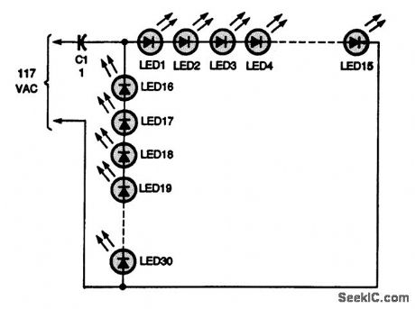
This circuit lets you light up two separate 15-light strings from a single power source. On the positive half cycle of the 60-Hz ac waveform, LEDs 1 through 15light, and on the negative half cycle, LEDs 16 through 30 light. Because the eye's response is much slower than 60 Hz, both strings appear to be on at the same time. (View)
View full Circuit Diagram | Comments | Reading(923)
VARIAVLE_FREQUENCY_LED_FLASHER
Published:2009/7/13 20:17:00 Author:May
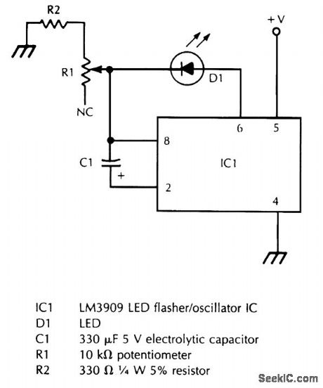
R1 varies the flash rate, and R2 limits the minimum resistance in the potentiometer circuit to prevent damage to D1 or IC1. (View)
View full Circuit Diagram | Comments | Reading(633)
| Pages:685/2234 At 20681682683684685686687688689690691692693694695696697698699700Under 20 |
Circuit Categories
power supply circuit
Amplifier Circuit
Basic Circuit
LED and Light Circuit
Sensor Circuit
Signal Processing
Electrical Equipment Circuit
Control Circuit
Remote Control Circuit
A/D-D/A Converter Circuit
Audio Circuit
Measuring and Test Circuit
Communication Circuit
Computer-Related Circuit
555 Circuit
Automotive Circuit
Repairing Circuit