LED and Light Circuit
VARIAVLE_FREQUENCY_LED_FLASHER
Published:2009/7/13 20:17:00 Author:May | From:SeekIC

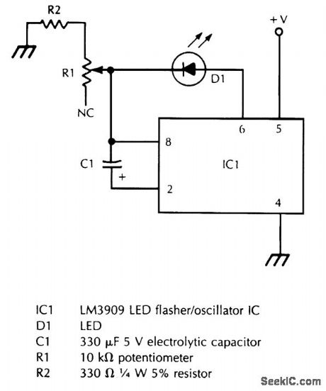
R1 varies the flash rate, and R2 limits the minimum resistance in the potentiometer circuit to prevent damage to D1 or IC1.
Reprinted Url Of This Article:
http://www.seekic.com/circuit_diagram/LED_and_Light_Circuit/VARIAVLE_FREQUENCY_LED_FLASHER.html
Print this Page | Comments | Reading(3)

Article Categories
power supply circuit
Amplifier Circuit
Basic Circuit
LED and Light Circuit
Sensor Circuit
Signal Processing
Electrical Equipment Circuit
Control Circuit
Remote Control Circuit
A/D-D/A Converter Circuit
Audio Circuit
Measuring and Test Circuit
Communication Circuit
Computer-Related Circuit
555 Circuit
Automotive Circuit
Repairing Circuit
Code: