LED and Light Circuit
VARYING_LCD_BIAS_CIRCUIT
Published:2009/7/13 20:29:00 Author:May | From:SeekIC

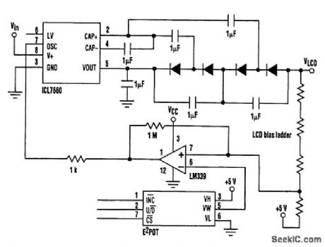
Large dot-matrix LCD drivers require a negative bias voltage of up to 24 V, depending on the LCD multiplex ratio One alternative is to combine the 7660 with a diode/capacitor voltage multiplier, using the 7660's internal square-wave generator as the signal source. This circuit will deliver an output of 37Vin-4Vf, thus generating approximately 24 V from a 9-V input. Additional stages could be added to the multiplier to allow 24 V to be generated from a 5-V regulated supply. In this circuit ,the output voltage is set by the input voltage, which might be inconvenient. If a variable voltage is required for contrast adjustment, Some form of microprocessor control over the output Voltage will be needed. One particular configuration used a Xicor E2POT to control the output by using a feedback circuit that pulls the oscillator pin of the 7660 low when the bias voltage exceeds the desired levels. This prevents further pumping of charge until the output returns to the required voltage The out-put ripple is set by the hysteresis resistor in the comparator circuit.
Reprinted Url Of This Article:
http://www.seekic.com/circuit_diagram/LED_and_Light_Circuit/VARYING_LCD_BIAS_CIRCUIT.html
Print this Page | Comments | Reading(3)

Article Categories
power supply circuit
Amplifier Circuit
Basic Circuit
LED and Light Circuit
Sensor Circuit
Signal Processing
Electrical Equipment Circuit
Control Circuit
Remote Control Circuit
A/D-D/A Converter Circuit
Audio Circuit
Measuring and Test Circuit
Communication Circuit
Computer-Related Circuit
555 Circuit
Automotive Circuit
Repairing Circuit
Code: