
Circuit Diagram
Index 696
70_MC_LOW_NOISE_I_F
Published:2009/7/16 2:34:00 Author:Jessie
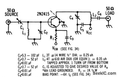
Noise figure ranges from 2 to 4 db depending on generator re sistance and emitter current. Power gain is 24 db.-Texas Instruments Inc., Solid. Slate Communications, McGraw-Hill, N.Y., 1966, p 312. (View)
View full Circuit Diagram | Comments | Reading(616)
JFET_CURRENT_SINK
Published:2009/7/13 5:01:00 Author:May

Simple circuit effectively raises load operating point of current-sen-sitive device by shunting current through JFET having nonlinear action. JFET type is not criti-cal. Applications include improvement of thyristor noise performance by diverting current around load. -V. Gregory, FET Current Sinks Raise Operating Points, EDN Magazine, Feb. 20, 1974, p 81. (View)
View full Circuit Diagram | Comments | Reading(640)
28_VAC_CURRENT_LIMITER
Published:2009/7/13 5:00:00 Author:May

Dual JFETs in voltage-sharing arrangement protect output of 28-VAC power amplifier. Transistors should be matched for IDSS. During positive half-cycle of input, Q2 operates as current Iimiter and Q1 as source follower. If Q1 does not supply enough current, drain voltage of Q2 drops and makes Q1 turn on further. Conversely, if Q1 supplies too much current, Q2 drain voltage rises and tends to turn Q1 off. On negative half-cycle, Q1 becomes limiter and Q2 is source follower. -J. P. Thompson, Current Limiter Protects Amplifier from Load Faults, EDN Magazine, June 5, 1978, p 148 and 150. (View)
View full Circuit Diagram | Comments | Reading(674)
LOG_LIMITER
Published:2009/7/13 5:00:00 Author:May

Installed between microphone and AF input connector of transmitter to increase averdge level of human voice and corresponding SSB transmitter output signal.Preamp U1 increases audio input level to over-come loss of following high-pass filter. Lowpass filter after logamp U2 eliminates all energy above about 2950 Hz. Last opamp U3 sets out.put level of processor for driving station transmitter properly. Overall amount of amplitude limiting is determined by setting of preamp gain control R4. Higffipass filter eliminates 60-Hz hum developed in audio system or in accessory equipment and reduces harmonic distortion generated by deeply pitched voice or by hum picked up from tape recorder or phone patch.Gain of opamp is determined by CR1-CR2, which give logarithmic response to audio input amplitude. Adjust R2, R17, and R19 for minimum distortion while applying 1-kHz sine wave to input.-R. Myers, A Quasi-Logarithmic Ana-Log Amplitude Limiter with Frequency-Domain Processing, QST, Aug. 1974, p 22-25 and 40. (View)
View full Circuit Diagram | Comments | Reading(1091)
HALF_WAVE_CONTROL
Published:2009/7/13 4:58:00 Author:May

Simple AC relay operates during positive alternations of AC source, with optoisolator providing complete isolation between control circuit and SCR handling inductive load. When input LED is energized by control pulse, photo-SCR of optoisolator conducts and provides gate current for turning on power SCR. 1N4005 diode protects SCR from back EMF transients of inductive load.-T, Mazur, Solid-State Relays Offer New Solutions to Many Old Problems, EDN Magazine, Nov. 20, 1973, p 26-32. (View)
View full Circuit Diagram | Comments | Reading(1380)
CB_TRANSMITTER_MIXER
Published:2009/7/13 4:58:00 Author:May
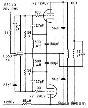
Requires only one crystal per channel in 27-Mc citizens band radiotelephones, by combining beating oscillator with balanced mixer. Receiver local oscillator with balanced mixer.Receiver local oscilator signal and even harmonics of beating oscillator frequency are cancelled in tuned symmetrical plate circuit.-M. E. Baird, Mixer Circuit Lowers Radiotelephone Costs, Electronics,34:47, p71. (View)
View full Circuit Diagram | Comments | Reading(1196)
AUTO_STETHOSCOPE
Published:2009/7/13 4:57:00 Author:May

The heart of the stethoscope is the NE5532 audio op amp, U1. That component directly drives low impedances and allows the use of headphones without adding another amplifier.This circuit uses an electret microphone and an audio amplifier using a NE5532 audio op amp as an automotive diagnostic tool. The mike is mounted in a probe or piece of tubing and placed near or on various parts of the engine or other components as an aid in diagnosis; the sound generated by the suspected part is used to determine possible problems. (View)
View full Circuit Diagram | Comments | Reading(1506)
PRECISION_CURRENT_SINK
Published:2009/7/13 4:57:00 Author:May

R1 serves as cur-rent-sensing resistor providing negative feed-back for opamp to enhance true current-sink nature of circuit. Both JFET and bipolar have inherently high output impedance as required for high-accuracy current sink.- FET Databook, National Semiconductor, Santa Clara, CA, 1977, p 6-26-6-36. (View)
View full Circuit Diagram | Comments | Reading(2744)
450_MC_TO_105_MC_WITH_2N2415
Published:2009/7/13 4:57:00 Author:May

Two-stage r-f amplifier has power gain of 20 db, noise figure of 4.5 db, and bandwidth of 10 Mc, 2N1407 local oscillator operates at 345 Mc.Conversion gain of mixer is 12 db. Total antenna to i-f conversion gain is 32 db.-Texas Instruments Inc. Solid-State Communications, McGraw-Hill, N.Y.1966, p307. (View)
View full Circuit Diagram | Comments | Reading(572)
SUMP_PUMP_CONTROL
Published:2009/7/13 4:56:00 Author:May

Impurities in water provide conductivity for completing circuit of transistor when water reaches level of sensing electrode, energizing relay that starts pump motor. Extra set of contacts on relay keeps motor running until water drops to predetermined lower level. Diodes are 1N4001 or equivalent, rated 1 A. Fuse should be chosen to pass normal motor current. Use 12-V double-pole relay. T1 is 300-mA filament transformer.-J. H.Gilder, Automatic Turn-On, Modern Electronics, Dec. 1978, p 78. (View)
View full Circuit Diagram | Comments | Reading(1801)
CAR_BATTERY_VOLTMETER_WITH_BAR_GRAPH_DISPLAY
Published:2009/7/13 4:55:00 Author:May

This uses an LM3914 bar-graph display, IC1, adapted to measure its own supply, so you simply wire it directly across the 12-V supply voltage (right way round-watch pins 2 and 3 carefully!). Ten LEDs, D1 to D10, will indicate the applied battery voltage, ranging from 1.5 to 15 V. The IC contains 10 internal comparators connected totem-pole-like, each sinking current through an LED. They compare an internal reference voltage against the chip's input voltage, at pin 5. Set the IC reference voltage with resistors R3 and R4 to just under 5 V. This means that one LED will light for every 500 mV (5 V reference/10 stages) increase in the signal. To enable this to be used to read a 12-V battery (the chip's own supply rail, in this case), resistors R1 and R2 are included as a divider: An input of roughly +15 V will cause D1 to light. When the voltage gradually falls, LEDs D2 to D10 will progressively illuminate. The circuit is set as a moving dot display. Connect pin 9 to the positive rail for a bar-graph display (not recommended because of the current consumption). Because the 10 outputs are effectively constant-current sinks, the LEDs will glow at a level independent of the changes in the supply rail; they won't dim when the rail drops. However, the first two or three display LEDs (D8 to D10) are superfluous in this application, because the LM3914 won't operate correctly below a rail of about +5 V. (View)
View full Circuit Diagram | Comments | Reading(3375)
POT_CONTROL
Published:2009/7/13 4:55:00 Author:May

Circuit makes current through linear pot a Iinear function of rotational angle of pot. Article gives design equations. Current i1 through R1 is used to charge C, which is periodically discharged by UJT when trigger voltage is reached. Frequency of output sawtooth is proportional to i1 and hence to angle of rotation of pots. To set up, adjust pots to give maximum sawtooth frequency and ad just preset R5 for re-quired maximum frequency. Set pots to other extreme and reset R3 for required minimum frequency. -A. Armit, Linear Current/Rotation Control, Wireless World, Dec. 1975, p 576. (View)
View full Circuit Diagram | Comments | Reading(1060)
DIGITAL_FIELD_STRENGTH_METER
Published:2009/7/13 4:54:00 Author:May

This field-strength meter uses a surplus LCD panel meter display, but any suitable unit (1 V full scale, etc.) can be used. RF is detected by a pair of 1N34 diodes and fed to an LM324 op amp acting as a dc amplifier whose gain is set via a 1-MΩ pot. The op-amp output drives the LCD panel meter. (View)
View full Circuit Diagram | Comments | Reading(2992)
AUTOMATIC_HEADLIGHT_DIMMER
Published:2009/7/13 4:53:00 Author:May

The circuit is designed to switch your car's lights from its high beams to its low beams when traffic approaches. With Q1 in moderate darkness, the variable resistors should be adjusted to produce no base current through Q2. When there are no approaching headlights to trigger the system, K1 is not energized, and its contacts remain closed. Relay K2 is energized, and the high-beam lights are on.When light from an approaching car shines on the phototransistor, the base current and collector current of the PNP transistor increase substantially, and K1 is energized. That automatically deenergizes K2 (a power-type relay fed directly by the car battery), shutting off the high-beam headlights and tuming on the low-beam lamps. Switch S1 should be conveniently located on the dash of the vehicle. Keep the switch turned off during the day so that the circuit will not leave your lights on in sunlight. (View)
View full Circuit Diagram | Comments | Reading(0)
TRIAC_TRIGGER
Published:2009/7/13 4:53:00 Author:May

National LM3909 IC is connected as pulse-transformer driver operating from standard 5-V logic supply. IC is biased off when logic input is high. With low logic input, IC provides 10-μs pulses for transformer at about 7 kHz. Trigger is not synchronized to zero crossings but will trigger within 8 V of zero for resistive load and 115-VAC line. Triggering oc cum at about 1 V, but trigger level can be changed by using other input resistors or bias dividers.- Linear Applications, Vol. 2, Na-tional Semiconductor, Santa Clara, CA, 1976, AN-154, p 7.
(View)
View full Circuit Diagram | Comments | Reading(2856)
AUDIO_CLIPPER_FILTER
Published:2009/7/13 4:52:00 Author:May

Improves seleetivity of communication receiver and prevents uncomfortablv loud volume in 500-ohm headphones. 88-mH toroid and 0.47-μF capaeitor form series resonant circuit at about 750 Hz with 6-dB bandwidth of 75 Hz. R2 and diodes form audio clipperwhose level is determined by forward conduction voltage of diodes. With ger-manium diodes for CR1-CR4 and silicon for CR5-CR6, each successive switch position boosts volume 6 dB. For low-impedance headphones, omit T1 and use 8 ohms for R2.-A, R Bloom, An Audio Clipper/Filter, QST, Aug. 1977, p 48. (View)
View full Circuit Diagram | Comments | Reading(903)
30_TO_325V_D_C
Published:2009/7/13 4:52:00 Author:May
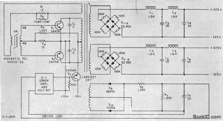
Use of transistors with high alpha cutoff frequency, along with loading networks across output bridge rectifiers,minimizes switching spikes in output. Control-loop amplifier provides overall regulation.-C. J. Biggerstaff, Reducing Spikes in D-C to D-C Converter Outputs, Electronics,34:42. p64-65. (View)
View full Circuit Diagram | Comments | Reading(750)
5_mA_WITH_VARIABLE_SLOPE_START
Published:2009/7/13 4:52:00 Author:May

UP-Low-cost NSL5022 LED typically has 1.6-V drop at 2 mA, to produce constant 0.9 V across 390-ohm emitter resistors in circuit shown. Use of two current sources, each feeding other's LED reference, eliminates all voltage defects except for small voltage-dependent changes in transistor parameters. Adding 240K slope resistor can eels these changes, holding current constant within 0.1% over supply voltage range of 5-20 V. Applications include use as voltage divider with gain, Q multiplier for tuned circuits, and bias compensation. -P. Lefferts, Variable Slope Current Source Starts at 2.5 v, EDN Magazine, Nov. 5, 1975, p 100. (View)
View full Circuit Diagram | Comments | Reading(595)
DRIVING_240_VAC_TRIAC
Published:2009/7/13 4:51:00 Author:May

Two Motorola MOC3011 optoisolators are used in series as interface between logic and triac controlling 240-VAC load. 1-megohm resistors across optoiso-lators equalize voltage drops across them. Choice of triacdepends on load to be handled.-P.O'Neil, Applications of the MOC3011 Tridc Driver, Motorola, Phoenix, AZ, 1978, AN-780, p5.
(View)
View full Circuit Diagram | Comments | Reading(1273)
TOUCH_SWITCH_3
Published:2009/7/13 4:51:00 Author:May

Finger on insulated metal plate applies small AC voltage (picked up by body) to FET Tr1 for amplification, to produce line-frequency square wave across R4 for application to memory section Tr3-Tr5. Charging of C3 through Tr3 and R5 produces DC output voltage across R8 that is fed to UJT Tr6 for triggering thyristor. C4 is discharged at about 10-ms intervals by Tr6 which operates from rectified AC line. For high voltage across R8, such as 4 V, thyristor is triggered early in AC cycle and maximum power is supplied to load. Diodes D4-D7 ensure that control is provided over both positive and negative half-cycles of line. The longer a finger is held on touch switch, the greater is the voltage across R8 and the more current there is through load. Removing finger turns off load, which can be lamps or other electric equipment.-R. Kreuzer, Touch-Switch Controller, Wireless World, Aug. 1971, p 389. (View)
View full Circuit Diagram | Comments | Reading(874)
| Pages:696/2234 At 20681682683684685686687688689690691692693694695696697698699700Under 20 |
Circuit Categories
power supply circuit
Amplifier Circuit
Basic Circuit
LED and Light Circuit
Sensor Circuit
Signal Processing
Electrical Equipment Circuit
Control Circuit
Remote Control Circuit
A/D-D/A Converter Circuit
Audio Circuit
Measuring and Test Circuit
Communication Circuit
Computer-Related Circuit
555 Circuit
Automotive Circuit
Repairing Circuit