Circuit Diagram
Index 699
OR_GATE_FOR_DIGITAL_VOLTMETER
Published:2009/7/16 3:45:00 Author:Jessie

Ground-level signal output is produced only when inputs from the two comparators are in different states. Transistor Q8 gates continuously-running clock oscillator into decade counters of voltmeter.-R. C. Weinberg, Modified Ramp Generator Develops High D-C Input Impedance, Electronics, 37:8, p 33-35. (View)
View full Circuit Diagram | Comments | Reading(633)
LOGIC_AND_BUFFER_AMPLIFIER
Published:2009/7/16 3:45:00 Author:Jessie

Designed to be driven by dual Schmitt trigger.-D. D. Robinson, Linear Microcircuits Scarce? Now You Con Breadboard Your Own, Electronics, 37:27, p 58-64. (View)
View full Circuit Diagram | Comments | Reading(669)
15_MC_RECEIVER
Published:2009/7/16 3:44:00 Author:Jessie

Operates 150 hours on 9 mercury cells, for applying command signals directly to brain of monkey. Thin-film pas sive components on three substrates reduce weight to 7 ounces.-W. Liben, Monkeys and Microelectronics, Electronics, 38:4, p 90-93. (View)
View full Circuit Diagram | Comments | Reading(569)
LINE_TRIGGERED_SQUARE_WAVE_GENERATOR
Published:2009/7/16 3:44:00 Author:Jessie

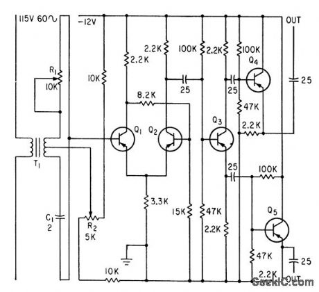
Bistable multivibrator Q1-Q2 is triggered by II through master phasing network R1-C1. R2 adjusts duty cycle. Output signal goes to frequency comparator that makes lab engine duplicate parameters recorded on magnetic tape during actual road run.-V. C. Vanderbilt and C. L. Zimmer, Magnetic Tape Recorder Programs Engine Dynamometer Tests, Electronics, 33:51, p 74-77. (View)
View full Circuit Diagram | Comments | Reading(537)
STORAGE_DIODE_SELECTION_MATRIX
Published:2009/7/16 3:44:00 Author:Jessie

Uses one diode per stored word. Four-word portion of 256-word matrix is shown. Activation of switch followed by driver drives selected diode sufficiently to permit flow of required read current. Write pulse is generated when read channel of both switch and driver are deactivated and write channel is activated.-I. Abeyta, M. M. Kaufman, and P. Lawrence, Monolithic Ferrite Memories, 1965 Fall Joint Computer Conference Preprints, Spartan Books, Washington, D. C., 1965.
(View)
View full Circuit Diagram | Comments | Reading(609)
MULTIMETER_CONDUCTANCE_ADAPTER
Published:2009/7/16 3:44:00 Author:Jessie

A 1.000-V reference is buffered by IC1, a TLC271, and is connected to J1 for use when measuring conductance. The voltage reference is derived from IC3, a 1.25-V temperature-compensat ed band-gap reference. The current drop developed by the component under test at J1 and J2 is converted by IC2 to an output voltage that can be displayed on a digital voltmeter. The output voltage is limited to a maximum of 2.0V and a minimum of 1.0 V. With the inverting input of IC2 at virtual ground, the maximum input current that can be measured is -2.0 μA. In reading the conductance of an unknown resistor (labeled RX, in the figure), -1.0 V is applied to J1, with J2 being at virtual ground. Based on the maximum input current that can be converted by IC2, the smallest resistance that can be measured is 500,000Ω. The values chosen for the circuit generate a conductance reading of 1.0 μmho/V, or 1.0 nmho/mV output. A 1.0-MΩ resistor will have a conductance of 1.0 pmho, or 1000 nmho. A 1.0-GΩ resistor would have a conductance of 1.0 nmho. The current-to-voltage conversion is set by R10, which gives an output of 1 V/μA, or 1 mV/nA. The lowest tolerance you should use for R10 is 1 percent. (View)
View full Circuit Diagram | Comments | Reading(2862)
TRANSDUCER_D_C_AMPLIFIER
Published:2009/7/16 3:43:00 Author:Jessie

Bank 1 of 24-channel telemetry sampling switch feeds transducer outputs in sequence to heat-stabilized low-drift d-c amplifier. Output goes to bank 2, for feeding f-m subcarrier oscillator, which in turn amplitude-modulates uhf transmitter.-A. Potton, Telemetry System for Testing Automobiles, Electronics, 33:43, p 57-59. (View)
View full Circuit Diagram | Comments | Reading(646)
LOW_POWER_FLIP_FLOP
Published:2009/7/16 3:43:00 Author:Jessie

2N3493 micropower transistors provide rapid switching with integrated construction. Power drain is only 6.6 mw.-R. W. McGinnis and W. D. Roehr, New Masking Techniques for Micropower Transistors, Electronics, 38:4, p 76-81. (View)
View full Circuit Diagram | Comments | Reading(795)
TTL_DIGITAL_MIXER
Published:2009/7/16 3:42:00 Author:Jessie

Uses two of 7400 TTL gates as crystal oscillator and other two gates as input buffers to 7474 D flip-flop serving as mixer. RF input signal must be lower than crystal frequency, and IF signal must be less than half crystal frequency. With 8-MHz crystal and 6.75-MHz RF signal, IF is 1.25 MHz. Common TTL 7474 can be used up to 25 MHz, 74H74 to 43 MHz, and 74S74 Schottky version to 100 MHz; Motorola MC12000 is good to 250 MHz.-G. H. Schrick, Introduction to the Digital Mixer, Ham Radio, Dec. 1973, p42-43. (View)
View full Circuit Diagram | Comments | Reading(3563)
LOCKED_PAIR
Published:2009/7/16 3:42:00 Author:Jessie

Ungrounded locked or Goto tunnel-diode pair permits logical inversion with no loss of speed or gain. Applications include converting analog television signals into pulse-code modulation.-C. L. Cohen, New Approach to Locked-Pair Tunnel-Diode Logic, Electronics, 35:31, p 46-47. (View)
View full Circuit Diagram | Comments | Reading(605)
THIN_FILM_AMPUFIER
Published:2009/7/16 3:42:00 Author:Jessie

Pulse amplifier with evaporated connections uses two thin-film triodes, two silicon monoxide aluminum capacitors, and four chromium and rhenium resistors.-F. W, Schenkel, Thin-Film Capacitance Elements: Which Is Best For Your Purpose, Electronics, 38:2, p 67-72. (View)
View full Circuit Diagram | Comments | Reading(596)
AUDIBLE_TURN_SIGNAL_INDICATOR_1
Published:2009/7/16 3:42:00 Author:Jessie

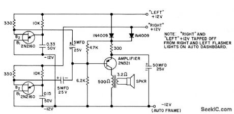
Produces two different tones in synchronism with turn-signal flashers.Diodes prevent short-circuit. For auto with negative ground.- Transistor Manual, Seventh Edition, General Electric Co,. 1964, p 381. (View)
View full Circuit Diagram | Comments | Reading(738)
SCHMITT_TRIGGER
Published:2009/7/16 3:42:00 Author:Jessie

Dual diode-coupled version for integrated construction uses eight resistors.-D. D. Robinson, Linear Microcircuits Scarce? Now You Can Breadboard Your Own, Electronics, 37:27, p 58-64. (View)
View full Circuit Diagram | Comments | Reading(0)
LOW_COST_INVERTER_AND_NOR_LOGIC
Published:2009/7/16 3:42:00 Author:Jessie

Inexpensive germanium pnp mesa switching transistor is used in basic inverter for high-speed computer circuits. Nor circuit is obtained by connecting other input stages to common collector load.-P. A. Mclnnis, Low-Cost Computer Circuits, Motorola Applica tion Note AN-130, Nov. 1965. (View)
View full Circuit Diagram | Comments | Reading(698)
MEASURING_SWITCHING_TIME_OF_IC_GATE
Published:2009/7/16 3:41:00 Author:Jessie

Used for and gates. To measure t1, S1 is opened, input pulse of Q1 is adjusted to give Q1 output fall time of 3 nsec/v slope for 2.5 v, and S1 is closed to measure t2.-Integrctted Circuits, FEE, 12:3, p 78. (View)
View full Circuit Diagram | Comments | Reading(560)
8_30_MHz_AMATEUR_BANDS
Published:2009/7/16 3:41:00 Author:Jessie

Will convert any frequency in tuning range to IF value between 3.5 and 4 MHz. Requires only three transistors and one IC. D1 and D2 can be germanium or silicon, such as 1N914 D3 is rectifier diode. Q2 can be almost any general-purpose high-frequency transistor. Two of gates in SN7400N TTL IC serve as crystal oscillator, and other two gates are buffers for detector diodes D1 and D2. Diodes are modulated by VCO Q2. Detector out, put is amplified and filtered by Q1 to produce control voltage for tuning D3. Output from mixer Q3 is untuned, with RFC as drain load element. -R. Megirian, High Frequency Utility Converter, 73 Magazine, June 1977, p 50-53. (View)
View full Circuit Diagram | Comments | Reading(1649)
EMITTER_COUPLED_TRANSISTOR_AND_GATE
Published:2009/7/16 3:41:00 Author:Jessie

Design gives manufacturing simplicity for integrated circuits without current hogging, but requires two power supplies. QD will con duct and QA QB, and QC will be off when any of input A, B, or C are below 0.2V.-A. E. Skoures, Choosing Logic for Microelectronics, Electronics, 36:40, p 23-26. (View)
View full Circuit Diagram | Comments | Reading(677)
F_M_RECEIVER
Published:2009/7/16 3:41:00 Author:Jessie

Multipurpose integrated-circuit chip consisting of six resistors and two identical transistors in cascode amplifier con figuration serves three different functions in single-frequency 100-Mc f-m receiver. Although discrete components are used in, digital discriminator, circuit requirements and component values here are compatible with monolithic techniques.-R. L. Sanquini, Multipurpose Chips Cut Costs of F-m Receiver, Electronics, 39:10, p 80-82. (View)
View full Circuit Diagram | Comments | Reading(997)
9_MHz_CRYSTAL_WITH_MULTIPLIER
Published:2009/7/16 3:40:00 Author:Jessie

Uses two sections of RCA CA3028A differential amplifier as Colpitts oscillator U1C feeding U1B which can be either amplifier or multiplier depending on values used for output tuned circuit. U1A is not used. Unmarked resistors are on IC.-D. DeMaw, Understanding Linear ICs, QST, Feb. 1977, p 19-23. (View)
View full Circuit Diagram | Comments | Reading(892)
BASIC_RCTL_LOGIC
Published:2009/7/16 3:40:00 Author:Jessie

Transistors used provide ultrahigh switching speed for computers and have low stored charge along with gain-bandwidth product above 300 Mc. Circuit can readily be adapted as flip-flop, nor circuit, and Schmitt trigger.-W. D. Roehr, For Computers... Basic RCTL Circuits, Motorola Application Note AN-129, Nov. 1965. (View)
View full Circuit Diagram | Comments | Reading(692)
| Pages:699/2234 At 20681682683684685686687688689690691692693694695696697698699700Under 20 |
Circuit Categories
power supply circuit
Amplifier Circuit
Basic Circuit
LED and Light Circuit
Sensor Circuit
Signal Processing
Electrical Equipment Circuit
Control Circuit
Remote Control Circuit
A/D-D/A Converter Circuit
Audio Circuit
Measuring and Test Circuit
Communication Circuit
Computer-Related Circuit
555 Circuit
Automotive Circuit
Repairing Circuit