
Circuit Diagram
Index 694
MAGNETIC_FIELD_DETECTOR
Published:2009/7/13 5:19:00 Author:May
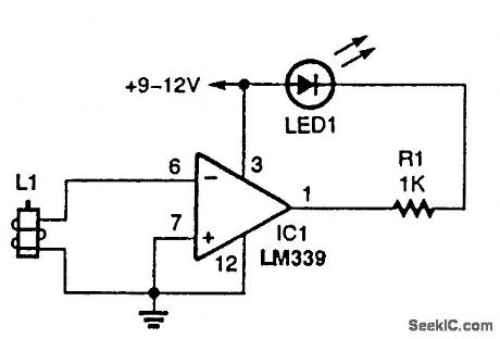
A relay coil makes a great magnetic-field detector. (View)
View full Circuit Diagram | Comments | Reading(2086)
WINDSHIELD_WIPER_CIRCUIT
Published:2009/7/13 5:19:00 Author:May

When the wipers are turned on, the switch in parallel with the cam-operated points keeps the motor running. When the switch is tumed off, the motor keeps running until the cam opens the points, stopping the motor when the wipers are in the PARK position. (View)
View full Circuit Diagram | Comments | Reading(819)
30_MC_I_F_USING_2N2410
Published:2009/7/16 2:39:00 Author:Jessie

Single stage gives power gain of 16 db, permitting use as final stage of i-f strip.-Texas Instruments Inc., Solid-State Communications, McGraw-Hill, N.Y., 1966, p 308. (View)
View full Circuit Diagram | Comments | Reading(672)
30_MC_I_F_USING_2N2188
Published:2009/7/16 2:39:00 Author:Jessie
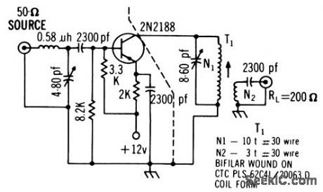
Circuit includes L-section to give generator resistance of 350 ohms from 50-ohm source. Power gain is13 db, noise figure 4 db, and bandwidth 5 Mc.-Texas Instruments Inc., Solid-State Communications, McGraw-Hill, N.Y., 1966, p 309. (View)
View full Circuit Diagram | Comments | Reading(681)
PREFERRED_AGC_AND_SQUELCH_CONTROL
Published:2009/7/16 2:39:00 Author:Jessie

Furnishes bias voltage for r-f and i-f stages of receiver, to minimize changes in output volume as input signal fades or as receiver is tuned to station having different signal strength. Additional output controls squelch tube that suppresses background noise in absence of input signal. Maximum i-f input is 7 v rms. Maximum d-c output level is -27 v for miniature tube and -35 v for subminiature.-NBS, Handbook Preferred Circuits Navy Aeronautical Electronic Equipment, Vol. I, Electron Tube Circuits, 1963, PC 63, p 63-2. (View)
View full Circuit Diagram | Comments | Reading(721)
RISE_AND_FALL_CONTROL
Published:2009/7/16 2:39:00 Author:Jessie

C1 controls range of rise and fall times, from 10 nsec for 10pf, to 10 millisec for 0.1 mfd. Used for testing pulse networks.-D. G. Larsen, Pulse Generator Controls Rise, Fall Time Independently, Electronics, 38:19, p 98-99.
(View)
View full Circuit Diagram | Comments | Reading(855)
MATCHING_LOW_Z_MIKE
Published:2009/7/13 5:18:00 Author:May

Single-transistor microphone impedance-matching circuit for low-impedance microphone feeds high-impedance input of amateur SSB transceiver. Circuit also boosts gain enough to meet transmitter input requirements.-C. Drumeller, Active Microphone Impedance Match, Ham Radio, Sept. 1973, p 67-68. (View)
View full Circuit Diagram | Comments | Reading(2750)
EARTH’s_FIELD_DETECTOR
Published:2009/7/13 5:18:00 Author:May
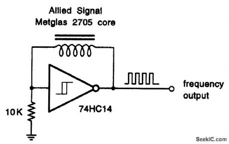
This elegantly simple earth's field detector uses a special variable permeability cored coil. The output frequency varies with orientation. (View)
View full Circuit Diagram | Comments | Reading(1041)
LIGHTS_ON_INDICATOR
Published:2009/7/13 5:17:00 Author:May

The buzzer (BZ) will sound if the ignition is off and the headlights are on (View)
View full Circuit Diagram | Comments | Reading(774)
35_W_TRANSMITTER
Published:2009/7/13 5:17:00 Author:May
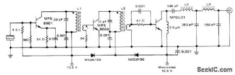
Class D circuit using economical plastic transistors operates from 12-V auto battery. 100% amplitude modulation requires about 2.5-W audio input. Modulator uses MSD6100 dual diode in modulated power supply system, with one diode in series with modulated supply voltage to MPS8000 driver to prevent driver from being down-modulated. Other diode maintains drive to final while final is being down-modulated, to make100% modulation easy to obtain. All coils are wound on 1/4-inch coil forms with No. 22 wire, with Carbonyl J 1/4× 3/8 inch cores in each. 2-turn secondaries are wound over bottom of primaries. L1 is 12 turns, L2 is 18, L3 is 7, and L4 is 5.-G. Young, A Class D Citizen's Band Transmitter Using Low-Cost Plastic Transistors, Motorola, Phoenix, AZ, 1975, AN-596. (View)
View full Circuit Diagram | Comments | Reading(1756)
FIELD_STRENGTH_METER
Published:2009/7/13 5:16:00 Author:May

This simple field-strength meter is great for tuning transmitters or antennas. It's a tool no ham should be without. The antenna is a 24-in whip. (View)
View full Circuit Diagram | Comments | Reading(0)
VISUAL_AND_AUDIBLE_HEADLIGHT_MONITOR
Published:2009/7/13 5:16:00 Author:May

If the LED in this circuit is flashing and the piezo sounder is buzzing, then your headlights are not on. (View)
View full Circuit Diagram | Comments | Reading(923)
FAST_CLAMP
Published:2009/7/13 5:16:00 Author:May

Smaller capacitance of temperature-compensated reference diodes allows clamping of faster pulses than is possible with ordinary zeners. Diagram shows positive 6.4-V diode clamp at ground potential. For smaller zener voltages, connect diode to more negative potential. Device Iimits only positive peaks; for negative peaks, reverse connections to 1N4570A. To clamp both polarities, use two units in parallel, oppositely connected.-W.Walloch, Clamp Fast Pulses with one Component, EDN Magazine, AprilG, 1974, p 76. (View)
View full Circuit Diagram | Comments | Reading(753)
VOLTAGE_CONTROLLED_OSCILLATOR
Published:2009/7/13 5:15:00 Author:May

Simple circuit,using feedback to maintain accuracy,converts 0 to 3V d-c linearly to 0 to 400 cps.Uses differential amplifier that amplifies difference between input and feedback signals and feeds frequency-determining output to Shockley four-layer diode oscillator-J. D.Long, Feedback linearizes Voltage-To-Frequency Converter, Electronics, 34:35, p48. (View)
View full Circuit Diagram | Comments | Reading(0)
CAPACITOR_DISCHARGE_IGNITION_CIRCUIT
Published:2009/7/13 5:15:00 Author:May

This ignition circuit consists of a dc-to-dc converter delivering 250 to 300 V to a 1.5-mF capacitor, and discharging it through the ignition coil primary upon the opening of the distributor points. SCR is triggered by the opening of the distributor points via inverter and pulse shaper Q3 and associated components. This circuit is typical of CD ignition systems. T1 is a special transformer for this circuit, but any suitable dc-to-dc converter transformer and circuit that delivers 250 Vdc (or more) can be used. (View)
View full Circuit Diagram | Comments | Reading(3989)
CLIPPER_STROBE
Published:2009/7/13 5:14:00 Author:May

Combination strobe and clipper built around 741C opamp provides two basic functions. First, strobe input of 5 V can reduce gain of amplifier to nearly zero by shorting output to input. Second, clipping function holds all outputs below predetermined level. When used in integrator, circuit provides constant rate of discharge for integrating capacitor. Clipping is done by four-diode bridge having three extra diodes acting as zener. Strobe function is provided by four-diode bridge alone, with strobing input circuit having single-ended input and differential output All transistors are 2N2219,and all diodes are 1N914.-L .Strahan,op Amρ Control Without Reays,EDN /EEE Magazine,Aug,15,1971,p 41-42.
(View)
View full Circuit Diagram | Comments | Reading(623)
VOICE_OPERATED_GATE
Published:2009/7/13 5:13:00 Author:May

Uses four ICs, two transistors, and two diodes to accomplish preamplification, bandpass filtering, and audio gating, as replacement for voice-operated relay in SSB transceiver having carbon microphone, Logic output (with choice of 1 or 0) serves as turn-on signal for other sections of system being voice-controlled. Low-pass and high-pass active filter pair provides equivalent of 300-3000 Hz bandpass filter with 40 dB rolloff per decade at each edge, to discriminate against ambient noise. Q1 is FET constant-current source for carbon microphone, feeding preamp U1 that provides voltage gain of about 100 and output of about 3 VRMS. Next two sections of quad opamp U1 are active filters, and last section of U1 is active diode detector in which opamp linearizes detector CR1-CR2. Rectified audio is averaged by U2 to give smoothed long positive pulse with duration of audio burst.Schmitt trigger U3 sharpens pulse and makes it compatible with CMOS logic. Inverter Q2 turns on analog gate U4 when audio signal is present.-H. Olson, Voice-Operated Gate to Replace Voice-Operated Relays for Carbon Microphones, Ham Radio, Dec. 1977, p 35-37. (View)
View full Circuit Diagram | Comments | Reading(1193)
INTERMITTENT_WINDSHIELD_CIRCUIT
Published:2009/7/13 5:12:00 Author:May

Basic timing is accomplished by the 555 IC. The resistor and capacitor network on pins 6, 7, and 8 sets the minimum delay at 2 s and the maximum at 20 s. The 555 output on pin 3 drives a 2N3906 PNP transistor to provide the proper input to the IRF740 power MOSFET. The MOSFET does the work and switches the wiper motor on at the end of the delay time. The wiper circuit uses a cam and switch arrangement on the drive assembly to cause the wiper blades to park in the proper place when the wipers are turned off. This cam switch is open when the blades are parked; the dashmounted wiper switch is in parallel with the cam switch. The intermittent circuit is wired to the cam switch as shown. When activated, and with the dash switch in the OFF position, the power MOSFET puts a ground on one side of the wiper motor, and the motor starts running. Shortly afterwards, the cam switch closes and forces the motor to continue running (regardless of the MOSFET's on/off status) until the PARK position is reached and the cam switch opens. The motor then stops, and one cycle is complete. (View)
View full Circuit Diagram | Comments | Reading(1713)
42O_MC_OSCILLATOR_MIXER
Published:2009/7/13 5:10:00 Author:May
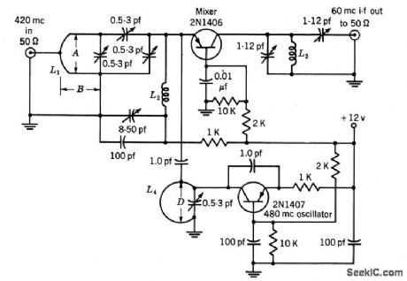
Common-base mixer is used with 480-Mc oscillator to give 60-Mc i-f output, with 10 db average conversion gain.-Texas Instruments Inc. Tran-sistor Circuit Design, McGraw-Hill, N.Y. 1963, p327. (View)
View full Circuit Diagram | Comments | Reading(1249)
MICROPOWER_FIELD_DETECTOR_FOR_470_MHz
Published:2009/7/13 5:10:00 Author:May

This circuit, which was tested at 470 MHz, contains a couple of improvements over the standard L/C-with-whip field-strength meter. The 0.4-wavelength section presents an efficient, low-impedance match to the base of the quarter-wave whip, but transforms the received energy to a relatively high voltage at the diode for good sensitivity. Biasing the detector diode improves the sensitivity by an additional 10 dB. The detector diode's bias point is monitored by an LTC1440 ultra-low-power comparator and by a second diode, which serves as a reference. Schottky diode D1 rectifies the incoming carrier and creates a negative-going bias shift at the noninverting input of the comparator. Note that the bias shift is sensed at the base of the antenna, where the impedance is low, rather than at the Schottky, where the impedance is high. This introduces less disturbance into the tuned antenna and transmission-line system. The falling edge of the comparator triggers a one-shot, which temporarily enables answer-back and other pulsed functions. Total current consumption is approximately 5 μA. Alternatively, a discrete one-shot constructed from a quad NAND gate draws negligible power. Sensitivity is excellent. The finished circuit can detect 200 mW radiated from a reference dipole at 100 ft. Range, of course, depends on operating frequency, antenna orientation, and surrounding obstacles; in the clear, a more reasonable distance, such as 10 ft, can be covered at 470 MHz with only a few milliwatts. All selectivity is provided by the antenna itself. Add a quarter-wave stub (shorted with a capacitor) to the base of the antenna for better selectivity and improved rejection of low-frequencysignals. (View)
View full Circuit Diagram | Comments | Reading(774)
| Pages:694/2234 At 20681682683684685686687688689690691692693694695696697698699700Under 20 |
Circuit Categories
power supply circuit
Amplifier Circuit
Basic Circuit
LED and Light Circuit
Sensor Circuit
Signal Processing
Electrical Equipment Circuit
Control Circuit
Remote Control Circuit
A/D-D/A Converter Circuit
Audio Circuit
Measuring and Test Circuit
Communication Circuit
Computer-Related Circuit
555 Circuit
Automotive Circuit
Repairing Circuit