Automotive Circuit
INTERMITTENT_WINDSHIELD_CIRCUIT
Published:2009/7/13 5:12:00 Author:May | From:SeekIC

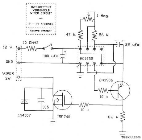
Basic timing is accomplished by the 555 IC. The resistor and capacitor network on pins 6, 7, and 8 sets the minimum delay at 2 s and the maximum at 20 s. The 555 output on pin 3 drives a 2N3906 PNP transistor to provide the proper input to the IRF740 power MOSFET. The MOSFET does the work and switches the wiper motor on at the end of the delay time. The wiper circuit uses a cam and switch arrangement on the drive assembly to cause the wiper blades to park in the proper place when the wipers are turned off. This cam switch is open when the blades are parked; the dashmounted wiper switch is in parallel with the cam switch. The intermittent circuit is wired to the cam switch as shown. When activated, and with the dash switch in the OFF position, the power MOSFET puts a ground on one side of the wiper motor, and the motor starts running. Shortly afterwards, the cam switch closes and forces the motor to continue running (regardless of the MOSFET's on/off status) until the PARK position is reached and the cam switch opens. The motor then stops, and one cycle is complete.
Reprinted Url Of This Article:
http://www.seekic.com/circuit_diagram/Automotive_Circuit/INTERMITTENT_WINDSHIELD_CIRCUIT.html
Print this Page | Comments | Reading(3)

Article Categories
power supply circuit
Amplifier Circuit
Basic Circuit
LED and Light Circuit
Sensor Circuit
Signal Processing
Electrical Equipment Circuit
Control Circuit
Remote Control Circuit
A/D-D/A Converter Circuit
Audio Circuit
Measuring and Test Circuit
Communication Circuit
Computer-Related Circuit
555 Circuit
Automotive Circuit
Repairing Circuit
Code: