
Circuit Diagram
Index 686
ELECTRONIC_EXPERIMENTERS_HANDBOOK
Published:2009/7/13 20:16:00 Author:May

The circuit diagram for the 1-s flasher is based on an operational amplifier that is biased by R1, R2, and R3 to act as a form of Schmitt trigger. The output goes to the low state if the inverting input is taken above 2/3V+, and high if it istaken below 1/3V+. The output, therefore, goes high initially, but C2 soon charges to 2/3V+ via R4, and then the output, goes low. Capacitor C2 then discharges to 1/3V+ via R4, sending the output high again, and producing continuous oscillation. ResistorR4 is adjusted to give an operating frequency of 1 Hz. The 1-s flasher can be calibrated against a watch or clock with asecond hand by empirical means. The output of IC1 is coupled to the LED indicator, D1, by way of dc blocking capacitor C3and current-limiting resistor R5, and the LED is briefly pulsed on as the output voltage swings positive. Diode D2 ensures that there is both a charge and a discharge path for C3 so that the output signal is properly coupled to D1. The current consumption of the unit is about 2 mA. (View)
View full Circuit Diagram | Comments | Reading(772)
FREQUENCY_TO_D_C_CONVERTER
Published:2009/7/13 20:15:00 Author:May

Used in place of costly frequency meter for frequency measurements from 10 cps to 1 Mc,having almost any input waveform. Overcall accuracy is 3%. Medium-power 12-v zener should be used to stabilize supply voltage.-T. Mollinga, Frequency-to-DC Converter for Lob Measurements, EEE, 12:8, p84. (View)
View full Circuit Diagram | Comments | Reading(609)
NEON_LAMP_FLASHER
Published:2009/7/13 20:13:00 Author:May
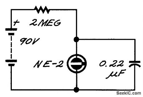
The neon lamp has negative dynamic resistance-the voltage across it falls while conduction is increasing. As a result, it flashes on and off. (View)
View full Circuit Diagram | Comments | Reading(820)
POWER_CONVERTER
Published:2009/7/13 20:12:00 Author:May

Silicon transistor version gives 15w output from 24-V supply at 70% efficiency, while germanium version gives over 100w at 90% efficiency. With germanium transistors, diode D1 and supply voltage must bereversed.-T.R.Pye, Design of Transislor Power Converters, Electronics, 32:36, p56-58; (View)
View full Circuit Diagram | Comments | Reading(1516)
FREQUENCY_TO_VOLTAGE_CONVERTER
Published:2009/7/13 20:09:00 Author:May

Linear staircase generator delivers d-c output voltage proportional to repetition frequency of input pulses while reiecting short-duration spurious noise pulses.-M. Merlen and D.Grossman, Interrogator Circuit Can Tell Good Data from Bad, Electronics, 37:20, p58-59. (View)
View full Circuit Diagram | Comments | Reading(1858)
COMMUNITY_TV_UP_CONVERTER
Published:2009/7/13 20:07:00 Author:May

Uses tunnel-diode oscillator.- Transistor Manual. Seventh Edition,General Electric Co.1964.p359 (View)
View full Circuit Diagram | Comments | Reading(589)
CRYSTAL_CONTROLLED_CB_CONVERTER
Published:2009/7/13 20:05:00 Author:May

Uses tunnel-diode oscillator.- Transistor Manual, Seventh Edition,General Electric Co.1964.p358 (View)
View full Circuit Diagram | Comments | Reading(663)
12_TO_162V_D_C_CONVERTER
Published:2009/7/13 19:57:00 Author:May

Simple and efficient saturating-core inverter provides 10w output with efficiency of 80%,using operating frequency of about 8.5kc,- Transistor Manual, Seventh Edition, General Electric Co.1964,p237 (View)
View full Circuit Diagram | Comments | Reading(1588)
THRIFTY_LED_FLASHER
Published:2009/7/13 11:51:00 Author:May

The dual complementary pair of switching FETs and inverter contained in a CD4007 CMOS IC enables an LED flasher to be made that uses very little energy. The IC is arranged as a three-inverter oscillator. Resistors R4 and R5 in series with the drains of one pair of FETs ensure that the drive current for the following pair of FETs is tiny. The high time of the oscillator is determined by network R3-C1, and its low time by R2-C1 (D1 is then cut off so that R3 is inactive). The LED is provided with current during the high time of the oscillator by T1. The level of this current is determined by R6.The values of R2,R3, and C1 cause an LED OFF time of 1 s and an ON time of 1 ms. Because the high-efficiency diode draws a current of30 mA, its lighting will be clearly visible. A standard 9-V battery will give continuous operation for about three years. (View)
View full Circuit Diagram | Comments | Reading(2561)
15_V_LED_FLASHER
Published:2009/7/13 11:48:00 Author:May
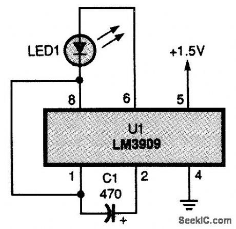
The LM3909 is one of the easiest-to-use LED flashers around. It can run for years using a stan-dard D cell. (View)
View full Circuit Diagram | Comments | Reading(0)
LIGHT_FLASHER
Published:2009/7/13 11:47:00 Author:May
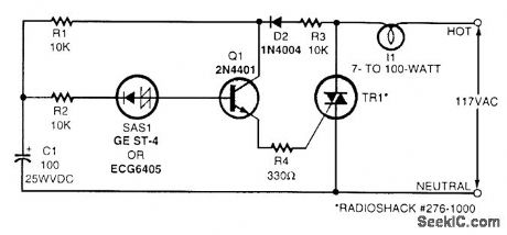
Shown here is a simple flasher circuit. With the component values shown, the flash rate is approximately once per second. The incandescent-lamp load glows at half brightness for about one-third of the total flasher period and is off for the remaining two-thirds. Electrolytic capacitor C1 charges during the positive half-cycle of the ac waveform through R1, R3, and D2. When the voltage across the capacitor reaches the break-over voltage of the silicon asymmetrical switch (SAS1), the capacitor starts to discharge through R2, SAS1, Q1, R4, and the triac. Emitter follower Q1 is driven by the discharge current from C1, and it, in turn, provides gate drive for the triac. Thus, the triac conducts and the light glows while C1 discharges. The lamp goes dark when C1 is depleted of charge and remains dark until the ac power waveform goes positive again and charges the capacitor sufficiently. The triac should be triggered into conduction by a gate current of no more than 5 mA. The flash rate can be varied by changing the value of capacitor C1. Using more capacitance results in a slower flash rate, and less capacitance results in a faster flash rate. (View)
View full Circuit Diagram | Comments | Reading(880)
MULTIPLE_FLASHING_LED_LIGHT_STRING
Published:2009/7/13 11:44:00 Author:May
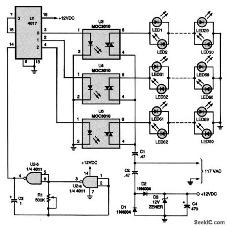
This circuit offers up to 10 strings of LEDs that turn on one row at a time in a sequential manner; for the sake of space and simplicity, only three strings are shown. The LED pairs could be all one color, mixed red and green, or any combination of colors. C2, C4, and D1 to D3 make up a 12-Vdc power supply for the five ICs. Two gates of a 4011 quad two-input NAND gate, U2-a and U2-b, are connected in a low-frequency oscillator circuit. Resistor R1 controls the oscillator's frequency.The oscillator supplies a clock output to U1, a 4017 decade counter/divider, which operates as a counter that can be programmed to count from 0 to 9. With each clock pulse, the 4017 makes a single step up in count from 0. The first output, at pin 3, supplies voltage to the LED in U3, a 3010 optocoupler, turning on the IC's triac and lighting the first string of LEDs. The next clock pulse steps the 4017 to the next output, at pin 2, and repeats the sequence for that string. As each new lightstring turns on, the preceding string turns off, giving the effect of a climbing string of lights. Changing the setting of R1 will change the rate at which the strings turn on and off. If you want to add additional light strings beyond what is shownin the figure, simply duplicate the circuitry for the light strings as shown and connect to the appropriate output of the 4017, U1. You will also have to connect the first unused output to pin 15. If you use the maximum of 10 strings, pin 15 should be connected to ground. (View)
View full Circuit Diagram | Comments | Reading(1710)
MULTIPLE_LED_FLASHER
Published:2009/7/13 11:40:00 Author:May

This is a circuit diagram for driving multiple LEDs from a single LM3909 flasher chip. (View)
View full Circuit Diagram | Comments | Reading(1677)
12_V_LED_FLASHER_1
Published:2009/7/13 11:37:00 Author:May


The figure shows a 12-V LED flasher configuration. (View)
View full Circuit Diagram | Comments | Reading(958)
AUDIO_DRIVEN_XENON_TUBE_FLASH_CIRCUIT
Published:2009/7/13 11:32:00 Author:May

This circuit uses a Xenon flashtube to create a very real lightning effect. It can be driven in one of two ways: by sound input or by straight repeated flashes, depending on where switch 2 is positioned. When producing straight flashes, the rate is determined by pot R7. If the switch is set to be triggered by sound, the sensitivity is determined by the level of the sound driving the transformer TX2 and the setting of pot R10. This circuit uses high voltages (over 4000 V for the trigger), and extreme care should be taken by anyone that builds it. The high-voltage capacitors can hold dangerous voltages for some time (even after the circuit has been unplugged). Strong caution concerning part polarity is highly urged. (View)
View full Circuit Diagram | Comments | Reading(1770)
MODEL_AIRCRAFT_LED_FLASHER
Published:2009/7/13 11:28:00 Author:May

This circuit was used to simulate machine gun firing on a model aircraft, but it can also be used for other applications. (View)
View full Circuit Diagram | Comments | Reading(1062)
12_V_LED_FLASHER
Published:2009/7/13 11:26:00 Author:May

This is the circuit diagram of an LED flasher suitable for 12-V operation. The liming formulas are also shown. (View)
View full Circuit Diagram | Comments | Reading(813)
SINGLE_LED_FLASHER
Published:2009/7/13 11:25:00 Author:May

This is a circuit diagram of an LED flasher with few components. (View)
View full Circuit Diagram | Comments | Reading(1247)
RAINBOW_FLASHER
Published:2009/7/13 11:24:00 Author:May

This device flashes a multicolor RGB LED in various colors, in a sequence and speed determined by the PIC 16C54 software. The LED is by Cree Electronics. (View)
View full Circuit Diagram | Comments | Reading(2124)
MODEL_FIRE_ENGINE_FLASHER_CIRCUIT
Published:2009/7/13 11:20:00 Author:May

This circuit was designed to add both a blue flashing light sequence and a two-tone siren effect to a model fire engine. IC1 is a quad NAND Schmitt trigger, and IC1a provides a low-frequency waveform, which is inverted by IC1b. Complementary outputs are obtained, which drive transistors TR1 and TR2. These driver transistors operate D1 and D2, which are two blueLEDs. The model had a blue translucent molding on its roof and yielded a surprisingly realistic effect. The outputs fromIC1a and IC1b are also used to control gated astables IC1c and IC1d, which are set to oscillate at different frequencies to simulate a typical British two-tone siren, sounded by WD1, a piezo disk. Battery B1 should be an alkaline or rechargeable9-V type because the current consumption is relatively high. S1 was a slide switch fitted on the rear of the vehicle.The sounder is optional.
(View)
View full Circuit Diagram | Comments | Reading(1471)
| Pages:686/2234 At 20681682683684685686687688689690691692693694695696697698699700Under 20 |
Circuit Categories
power supply circuit
Amplifier Circuit
Basic Circuit
LED and Light Circuit
Sensor Circuit
Signal Processing
Electrical Equipment Circuit
Control Circuit
Remote Control Circuit
A/D-D/A Converter Circuit
Audio Circuit
Measuring and Test Circuit
Communication Circuit
Computer-Related Circuit
555 Circuit
Automotive Circuit
Repairing Circuit