LED and Light Circuit
LIGHT_FLASHER
Published:2009/7/13 11:47:00 Author:May | From:SeekIC

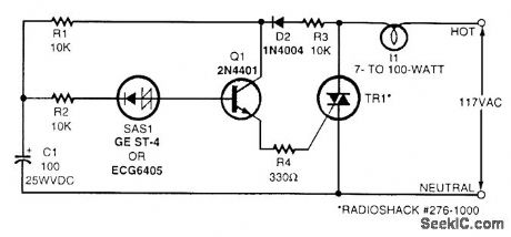
Shown here is a simple flasher circuit. With the component values shown, the flash rate is approximately once per second. The incandescent-lamp load glows at half brightness for about one-third of the total flasher period and is off for the remaining two-thirds. Electrolytic capacitor C1 charges during the positive half-cycle of the ac waveform through R1, R3, and D2. When the voltage across the capacitor reaches the break-over voltage of the silicon asymmetrical switch (SAS1), the capacitor starts to discharge through R2, SAS1, Q1, R4, and the triac. Emitter follower Q1 is driven by the discharge current from C1, and it, in turn, provides gate drive for the triac. Thus, the triac conducts and the light glows while C1 discharges. The lamp goes dark when C1 is depleted of charge and remains dark until the ac power waveform goes positive again and charges the capacitor sufficiently. The triac should be triggered into conduction by a gate current of no more than 5 mA. The flash rate can be varied by changing the value of capacitor C1. Using more capacitance results in a slower flash rate, and less capacitance results in a faster flash rate.
Reprinted Url Of This Article:
http://www.seekic.com/circuit_diagram/LED_and_Light_Circuit/LIGHT_FLASHER.html
Print this Page | Comments | Reading(3)

Article Categories
power supply circuit
Amplifier Circuit
Basic Circuit
LED and Light Circuit
Sensor Circuit
Signal Processing
Electrical Equipment Circuit
Control Circuit
Remote Control Circuit
A/D-D/A Converter Circuit
Audio Circuit
Measuring and Test Circuit
Communication Circuit
Computer-Related Circuit
555 Circuit
Automotive Circuit
Repairing Circuit
Code: