
Circuit Diagram
Index 683
TUNE_UP_AID
Published:2009/7/13 21:18:00 Author:May
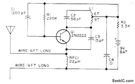
Superregenerative receiver circuit is modified to bring quenching frequency down into audio range, thereby giving many closely spaced carriers in region of 27 MHz. RF level across frequency range is essentially constant. Signal simplifies tune-up of front ends of CB units. Antenna is 6 feet of wire connected to emitter side of RFC, with 9 feet of wire on battery side of RFC as counterpoise. Combination, with circuit in center, can be hung vertically in tree if means can be provided for turning it off or removing battery when not in use. Drain is about 0.5 mA from 9-V battery.-E. A. Lawrence, Citizens Band Alignment Aid, 73 Magazine, April 1973, p 87-88. (View)
View full Circuit Diagram | Comments | Reading(3230)
ANALOG_GATE
Published:2009/7/16 2:00:00 Author:Jessie
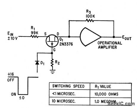
Output is -10.0025 V for +10 V input, and +9.9975 V for -10 V input.-M. Shipley Sr., Analog Switching Circuits Use Field-Effect Devices, Electronics, 37:32, p 45-50. (View)
View full Circuit Diagram | Comments | Reading(653)
BRIDGE_GATE_WITH_TOROID
Published:2009/7/16 1:59:00 Author:Jessie
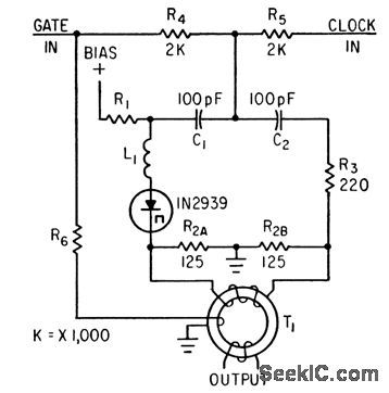
Portion of gate input signal is fed to wire threading output toroid, to cancel output spike of ac bridge.-F. W. Kantor, Tunnel-Diode Gate has Sub-nanosecond Rise Time, Electronics, 35:15, p 62-64. (View)
View full Circuit Diagram | Comments | Reading(543)
FM_DEMODULATOR
Published:2009/7/13 21:17:00 Author:May
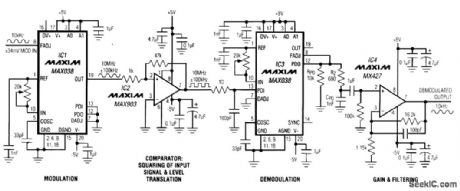
The frequencies at IC3's phase-detector output are the sum and difference of the frequencies at PDI and OUT. Thus, with appropriate cutoff frequency and gain, the low-pass filter (IC4) passes only the original 10-kHz signal to the demodulated output. The pole for this filter is set by the 16.2-kΩ and 100-pF components. The frequency response for IC3's PLL is set by RPD, CPD, and RZ, When the loop is in lock, PDI is in approximate phase quadrature with the output signal. Also, when in lock, the duty cycle at PDO is 50 percent, and PDO's average output current is 250 μ A. The current sink at FADJ demands a constant 250 μ A, so PDO outputs above and below that level develop a bipolar error voltage across RPD that drives the FADJ voltage input. Note: The MAX038's internal phase detector is a phase-only detector, producing a PLL whose frequency-capture range is limited by the bandwidth of its loop filter. For wider-range applications, consider an external phase-frequency detector. (View)
View full Circuit Diagram | Comments | Reading(0)
NOR_LOGIC_USING_SERIES_TRANSISTORS_FOR_AND_GATE
Published:2009/7/16 1:59:00 Author:Jessie
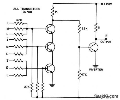

Requires inverter at output.- Transistor Manual, Seventh Edition, General Electric Co.,1964, p 179. (View)
View full Circuit Diagram | Comments | Reading(604)
AUTO_GUARDIAN_TRANSMITTER
Published:2009/7/13 21:17:00 Author:May
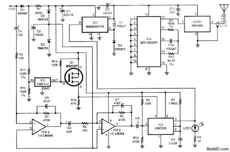
The circuit is powered by the vehicle's 12-V battery. A pair of zener diodes, D2 and D3, create two regulated voltage sources of 10.9 and 6.2 V. Integrated circuit IC2 contains a pair of identical op amps, which are cascaded. The negative input of IC2-a is ac-coupled to the 12-V bus so that it can detect a sudden sag in voltage caused by the current draw of the vehicle's dome lampswhen a door is opened. A change in battery voltage of 3 mV will cause a -6-V swing at the output of IC2-b, which is great enough to trigger IC3, a CMOS 555 timer chip. That IC is wired to operate as a one-shot pulse generator. An output pulse about 2[fr1/2] s long appears on pin 3 of IC3 when triggered by IC2-b. The output of IC3 is connected to the enable input of IC1, a switching-type voltage regulator. When IC1 is enabled, it outputs a regulated 3.3-Vdc power source for the transmitter portion of the circuit, encoder IC4 and transmitter module MOD1, When power is applied to the encoder, a series of pulse trains is generated that contain the address of the encoder. Those pulse trains are applied to pin 1 of the hybrid module to produce an RF signal with an on-off pulse modulation, sometimes called corn,plitude-shift keying. When the 2 1/2-s pulse time of IC3 is completed, the transmitter shuts down, returning to its dormant state.In order to prevent RE transmission while the vehicle is running, voltage detector IC5 uses R11 and R12 as a voltage divider to sense when the supply voltage rises above 12 V as a result of an alternator charging when the engine is running. Under that condition, the output of IC5 is open, turning off Q1. That holds the reset input of IC3 low, preventing the timer chip from responding to any trigger pulses from the amplifier. As a result, no transmission takes place. The HX1000 hybrid-transmitter module, MOD1, is a four-terminal device that contains a surface -acoustic -wave -stabilize d UHF oscillator. The oscillation frequency, 433.92 MHz, is stabilized and controlled by the resonant frequency of the internal surface-acoustic-wave filters, which also filter undesirable harmonics. The hybrid module is capable of delivering about I mW of power (0 dBm) into a 50-Ω load. It is connected to the trans-mitting antenna through a 50-Ω coaxial cable. (View)
View full Circuit Diagram | Comments | Reading(1516)
CAPACITOR_LEAKAGE_TESTER
Published:2009/7/16 1:57:00 Author:Jessie
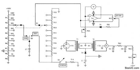
In this circuit, a capacitor is charged to a voltage near its working voltage, as selected by S1. Then S2 is placed in the TEST position, and high-resistance divider R10 to R18 is used to discharge it. The total resistance is 100 MΩ. Taps selected by S1 are used to reduce the voltage seen by the op-amp metering circuit to an appropriate value (around 3V). The discharge curve is watched on the meter. If it is too rapid, the capacitor might be leaky. This technique is useful for values of C that produce a sufficiently large time constant, 10s or more (C>0.1 μF). (View)
View full Circuit Diagram | Comments | Reading(2791)
FOUR_DIODE_TR_SWITCH
Published:2009/7/13 21:17:00 Author:May
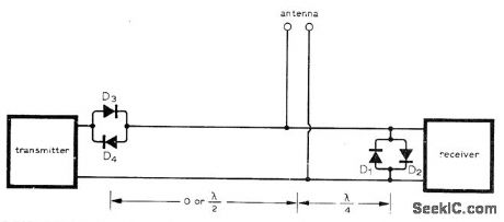
Circuit requires only two pairs of high-frequency switching diodes having current ratings appropriate for transmitter power. With diode pairs spaced as shown, impedance at T junction looking toward transmitter is infinite during reception because there is open circuit half a wavelength away created by nonconducting D3 and D4. Line is matched in receiver direction so all incoming power from antenna goes into receiver. When transmitter is on, D3 and D4 conduct and power flows toward antenna, while D1 and D2 also conduct and place short-circuit across receiver input.-A. Lieber, Passive Solid-State Antenna Switch, Wireless World, Jan. 1975, p 12. (View)
View full Circuit Diagram | Comments | Reading(708)
THREE_STATE_LOGIC
Published:2009/7/16 1:56:00 Author:Jessie
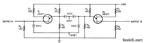
With no input pulse (state 1), output A is zero and output B is 1.5 v. With a positive input pulse (state 2),A and B are both 1.5 v. With a negative input pulse (state 3), A and B are both zero. A 12-v positive pulse at the reset terminal restores stale 1.-S. F. Summer, Two Unijunction Transistors Produce Three-State Circuit, Electronics, 39:1, p 100. (View)
View full Circuit Diagram | Comments | Reading(524)
TRIAC_CONTROL_WITH_OPTOISOLATOR
Published:2009/7/13 21:17:00 Author:May
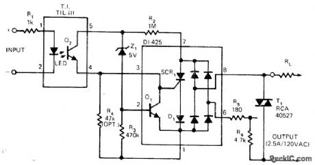
Dionics D1425 switchable bridge circuit controls 120-VAC line in optically isolated zero-crossing solid-state relay that can be used as trigger form power triac. Small AC devices, drawing under 5 W, can be switched directly in either random or zero-crossing mode.-High-Voltage Monolithic Technology Produces 200V AC Switching Circuit, EDN Magazine, April 5, 1975, p 121. (View)
View full Circuit Diagram | Comments | Reading(2933)
160_500_MHz_DIODE_RECEIVER
Published:2009/7/16 1:55:00 Author:Jessie
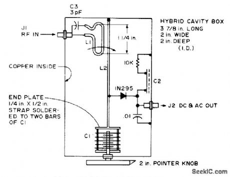
Cavity version of basic crystal detector was developed for use chiefly in 220-MHz and 450-MHz amateur bands. C1 is 25-pF tuning capacitor, and C2 is 1 x 2 inch brass plate insulated from sheet-copper cavity by 0.005-inch Teflon sheet or mica. L1 is 3-inch length of 1-inch copper strap.-B. Hoisington, Tuned Diode VHF Receivers, 73 Magazine, Dec. 1974, p 81-84. (View)
View full Circuit Diagram | Comments | Reading(885)
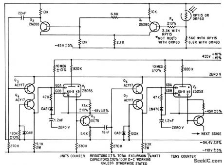
SHIFT_REGISTER
Published:2009/7/13 21:17:00 Author:May

Memory chain of 16 miniature logic tubes (three shown) serves as counter for weighing and batching.-M. E. Bond, Cold-Cathode Tubes as Triggers, Electronics, 38:7, p 76-85 (View)
View full Circuit Diagram | Comments | Reading(0)
SHUNT_CLIPPER
Published:2009/7/13 21:14:00 Author:May

When input voltage is above reference voltage, D1 is reverse-biased and input voltage passes through R1 to output.When negative peak of Ein exceeds Vref, opamp A1 turns D1 on to absorb input current from R1, thereby clamping output at level of Vref. If low output impedance is required, use 110 highspeed voltage follower as buffer amplifier.-W.G. Jung, IC Op-Amp Cookbook, Howard W.Sams, Indianapolis, IN, 1974, p 189-190. (View)
View full Circuit Diagram | Comments | Reading(1060)
AUXILIARY_NEGATIVE_dc_SUPPLY_FOR_BIAS_OR_REFERENCE_APPLICATIONS
Published:2009/7/16 1:55:00 Author:Jessie

In this circuit, IC1 (CD4009) is used as a square-wave oscillator at approximately 25 kHz. C1 and R1 set this frequency. C2, D1, D2, and C3 form a p-p rectifter, which outputs about -3.5 Vdc. This circuit should be useful where a small negative dc supply is required, but only positive dc voltages are available. (View)
View full Circuit Diagram | Comments | Reading(1023)
CONVEYOR_COUNTER
Published:2009/7/13 21:13:00 Author:May

Senses objects as small as 0.2 sq cm on moving conveyor at speeds up to 25 pps. -G. Jeynes, Using Cold Cathode Tubes to Count and Store, Electronics,38:8, p80-89.
(View)
View full Circuit Diagram | Comments | Reading(774)
NEON_INDICATOR_SCALER
Published:2009/7/13 21:10:00 Author:May


Battery-powered stage uses binary scaling circuit with nonsaturated temperature-compensated transistors, as elements of scale-of-64 circuit driving 4-dight mechanical register.-F.E. Armstrong. Battery Powered Portable Scaler.Electronics.33:19,p74-75 (View)
View full Circuit Diagram | Comments | Reading(671)
MAX038_HIGH_SPEED_FUNCTION_GENERATOR_CIRCUIT
Published:2009/7/13 21:07:00 Author:May

For enthusiasts who would like to experiment with this device for themselves, a simple circuit to get it up and running is shown. The only real problem with the MAX038 is inherent in its sheer speed. Maxim suggests careful layout on adouble-sided ground-plane PC board for best results. In practice, a single-sided PC board seems to work well, provided it has plenty of copper areas at ground potential, good decoupling, and guard tracks around signal paths carrying rectangularwaveforms, especially that from the sync output. The following component recommendations are offered:Resistors-0.6 W, 1-percent metal filmC1, C2, C3, and C5-ceramic diskC4 and C6-tantalum bead, 35 VCext-as required for frequency, between 47pF and 47μF, polyester or polystyrene (View)
View full Circuit Diagram | Comments | Reading(1447)
VLF_CONVERTER
Published:2009/7/13 21:05:00 Author:May

This very simple converter permits reception of the VLF 3- to 30-kHz band on a shortwave receiver covering the 6-MHz (49-m) shortwave broadcast band. T1 is an audio transformer of about 8 to 1000ΩThese can easily be purchased new or found in junked transistor radios. (View)
View full Circuit Diagram | Comments | Reading(0)
BATTERY_OPERATED_FLUORESCENT_LIGHT
Published:2009/7/13 21:00:00 Author:May
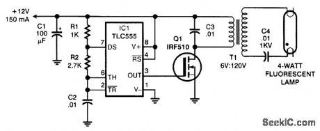
The circuit consists of a 20-kHz oscillator, a switching transistor to amplify its output, and a step up transformer. A 120- to 6-V power transformer is connected backward, using half of the 12-V side for 6 V. In the circuit, the transformer is working at considerably more than its rated voltage, but the high frequency keeps it from saturating. Although the lamp does not glow at full brightness, the circuit is energy-efficient, requiring only 150 mA. (View)
View full Circuit Diagram | Comments | Reading(2883)
GUNSHOT_COUNTER
Published:2009/7/13 20:57:00 Author:May

Loudspeaker serves as microphone for picking up loud noises such as from blasts, noisy auto engines, and children on roller skates. Each input shock wave drives grid of 1U4 negative and fires 1D21 strobotron, thereby dumping charge on 2.mfd capacitor from plate to ground through counter. Operates at up to 40 shots per second, fast enough for most automatic weapons fire.-R. L. lves , Shot Counter Uses Strobotron, Electronics, 31:33, p94-96. (View)
View full Circuit Diagram | Comments | Reading(759)
| Pages:683/2234 At 20681682683684685686687688689690691692693694695696697698699700Under 20 |
Circuit Categories
power supply circuit
Amplifier Circuit
Basic Circuit
LED and Light Circuit
Sensor Circuit
Signal Processing
Electrical Equipment Circuit
Control Circuit
Remote Control Circuit
A/D-D/A Converter Circuit
Audio Circuit
Measuring and Test Circuit
Communication Circuit
Computer-Related Circuit
555 Circuit
Automotive Circuit
Repairing Circuit