© 2008-2012 SeekIC.com Corp.All Rights Reserved.
Communication Circuit
AUTO_GUARDIAN_TRANSMITTER
Published:2009/7/13 21:17:00 Author:May | From:SeekIC

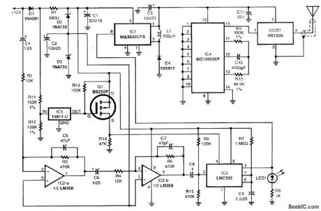
The circuit is powered by the vehicle's 12-V battery. A pair of zener diodes, D2 and D3, create two regulated voltage sources of 10.9 and 6.2 V. Integrated circuit IC2 contains a pair of identical op amps, which are cascaded. The negative input of IC2-a is ac-coupled to the 12-V bus so that it can detect a sudden sag in voltage caused by the current draw of the vehicle's dome lampswhen a door is opened. A change in battery voltage of 3 mV will cause a -6-V swing at the output of IC2-b, which is great enough to trigger IC3, a CMOS 555 timer chip. That IC is wired to operate as a one-shot pulse generator. An output pulse about 2[fr1/2] s long appears on pin 3 of IC3 when triggered by IC2-b. The output of IC3 is connected to the enable input of IC1, a switching-type voltage regulator. When IC1 is enabled, it outputs a regulated 3.3-Vdc power source for the transmitter portion of the circuit, encoder IC4 and transmitter module MOD1, When power is applied to the encoder, a series of pulse trains is generated that contain the address of the encoder. Those pulse trains are applied to pin 1 of the hybrid module to produce an RF signal with an on-off pulse modulation, sometimes called corn,plitude-shift keying. When the 2 1/2-s pulse time of IC3 is completed, the transmitter shuts down, returning to its dormant state.In order to prevent RE transmission while the vehicle is running, voltage detector IC5 uses R11 and R12 as a voltage divider to sense when the supply voltage rises above 12 V as a result of an alternator charging when the engine is running. Under that condition, the output of IC5 is open, turning off Q1. That holds the reset input of IC3 low, preventing the timer chip from responding to any trigger pulses from the amplifier. As a result, no transmission takes place. The HX1000 hybrid-transmitter module, MOD1, is a four-terminal device that contains a surface -acoustic -wave -stabilize d UHF oscillator. The oscillation frequency, 433.92 MHz, is stabilized and controlled by the resonant frequency of the internal surface-acoustic-wave filters, which also filter undesirable harmonics. The hybrid module is capable of delivering about I mW of power (0 dBm) into a 50-Ω load. It is connected to the trans-mitting antenna through a 50-Ω coaxial cable.
Reprinted Url Of This Article:
http://www.seekic.com/circuit_diagram/Communication_Circuit/AUTO_GUARDIAN_TRANSMITTER.html
Print this Page | Comments | Reading(3)

Article Categories
power supply circuit
Amplifier Circuit
Basic Circuit
LED and Light Circuit
Sensor Circuit
Signal Processing
Electrical Equipment Circuit
Control Circuit
Remote Control Circuit
A/D-D/A Converter Circuit
Audio Circuit
Measuring and Test Circuit
Communication Circuit
Computer-Related Circuit
555 Circuit
Automotive Circuit
Repairing Circuit
New published articles
Response in 12 hours

Code: