Basic Circuit
FOUR_DIODE_TR_SWITCH
Published:2009/7/13 21:17:00 Author:May | From:SeekIC

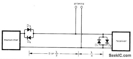
Circuit requires only two pairs of high-frequency switching diodes having current ratings appropriate for transmitter power. With diode pairs spaced as shown, impedance at T junction looking toward transmitter is infinite during reception because there is open circuit half a wavelength away created by nonconducting D3 and D4. Line is matched in receiver direction so all incoming power from antenna goes into receiver. When transmitter is on, D3 and D4 conduct and power flows toward antenna, while D1 and D2 also conduct and place short-circuit across receiver input.-A. Lieber, Passive Solid-State Antenna Switch, Wireless World, Jan. 1975, p 12.
Reprinted Url Of This Article:
http://www.seekic.com/circuit_diagram/Basic_Circuit/FOUR_DIODE_TR_SWITCH.html
Print this Page | Comments | Reading(3)

Article Categories
power supply circuit
Amplifier Circuit
Basic Circuit
LED and Light Circuit
Sensor Circuit
Signal Processing
Electrical Equipment Circuit
Control Circuit
Remote Control Circuit
A/D-D/A Converter Circuit
Audio Circuit
Measuring and Test Circuit
Communication Circuit
Computer-Related Circuit
555 Circuit
Automotive Circuit
Repairing Circuit
Code: