Measuring and Test Circuit
CAPACITOR_LEAKAGE_TESTER
Published:2009/7/16 1:57:00 Author:Jessie | From:SeekIC

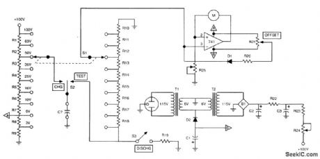
In this circuit, a capacitor is charged to a voltage near its working voltage, as selected by S1. Then S2 is placed in the TEST position, and high-resistance divider R10 to R18 is used to discharge it. The total resistance is 100 MΩ. Taps selected by S1 are used to reduce the voltage seen by the op-amp metering circuit to an appropriate value (around 3V). The discharge curve is watched on the meter. If it is too rapid, the capacitor might be leaky. This technique is useful for values of C that produce a sufficiently large time constant, 10s or more (C>0.1 μF).
Reprinted Url Of This Article:
http://www.seekic.com/circuit_diagram/Measuring_and_Test_Circuit/CAPACITOR_LEAKAGE_TESTER.html
Print this Page | Comments | Reading(3)

Article Categories
power supply circuit
Amplifier Circuit
Basic Circuit
LED and Light Circuit
Sensor Circuit
Signal Processing
Electrical Equipment Circuit
Control Circuit
Remote Control Circuit
A/D-D/A Converter Circuit
Audio Circuit
Measuring and Test Circuit
Communication Circuit
Computer-Related Circuit
555 Circuit
Automotive Circuit
Repairing Circuit
Code: