
Circuit Diagram
Index 688
CAPACITORLESS_NOTCH_FILTER
Published:2009/7/13 10:29:00 Author:May

The notch frequency for the filter is set by fnotch+[(ALP/AHP)×(RZ2/RZ1)]×f0where ALP and AHP are the gain from input to low-pass output at f=0 Hz,and the gain from input to high-pass output at f≤f0,respectively. Typically ((ALP/AHP)×(RZ2/RZ1)=1;therefore,fnotch=f0,and is gtven by f0=1/(2π)(RFC)where RF=RF1=RF2, and C=C1=C2. The -3-dB bandwidth is determined by the following relation∶BW-3dB=fnotch/Q, where BW-3dB=fH-fL. The Q of the filter affects the passband gainc(which should be adjusted to unity) and is related to the ratio of the resistances RZ3 to RZ1 and RZ3 to RZ2. In other words,Q=(RZ3/RZ1)=(RZ3/RZ2). Q also is related to RQ by the follOwing relation∶RQ=(25 kΩ/Q-1). (View)
View full Circuit Diagram | Comments | Reading(1054)
FUEL_PUMP_OSCILLATOR
Published:2009/7/16 3:17:00 Author:Jessie

Silicon transistor serves as switch that eliminates arcing contacts, permitting use of pump in explosive atmosphere, even inside fuel tank. Power transistor is in blocking oscillator circuit for driving solenoid plunger assembly of commercial electric fuel pump. Feedback winding was added to drive coil. Ratio of solenoid coil turns to feedback turns should be 4 to 1 to insure proper starting in cold weather.-H. F. Weber, Transistor Operated Fuel Pump Eliminates Arcing Contacts and Commutator Brushes, Motorola Application Note AN-175, Feb. 1966. (View)
View full Circuit Diagram | Comments | Reading(1078)
INFRARED_HOT_ENGINE_DETECTOR
Published:2009/7/16 3:16:00 Author:Jessie


Output relay resets parking meter to zero when lead sulfide detector senses heat of engine when parked car is started.-W. E. Osborne, Farewell To Free Time On City Parking Meters, Electronics, 37:32, p 72-74. (View)
View full Circuit Diagram | Comments | Reading(696)
NOTCH_FILTER_CIRCUIT
Published:2009/7/13 10:17:00 Author:May

This circuit is basically a noninverting amplifier with positive feedback. The negative feedback path is set to unity by a direct connection between the output terminal of the operational amplifier and the inverting (-) input. A frequency-selective RC network connects the output to the noninverting (+) input, providing some positive feedback. The center frequency is FC=1/2πR1(C1C2)1/2where FC is the center frequency in hertz, R1 is in ohms, and C1 and C2 are in farads. (View)
View full Circuit Diagram | Comments | Reading(1028)
TUNABLE_VLF
Published:2009/7/16 3:16:00 Author:Jessie
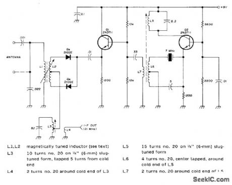
TUNABLE VLF-Gives tuning range of 10kHz to 150 kHz without bandswitching, for WWV transmissions on 20 and 60 kHz and for operation on no-license amateur band around 1750 meters. Uses inductive tuning with toroidal ferrite core L1-L2 that is magnetically biased by pair of 1/2-inch diameter button-type permanent magnets. Rotating one of magnets with respect to other varies flux through toroid, changing its permeability and inductance. Toroid uses 100 turns of stranded wire to give inductance variation from 100 μH to 12 mH (120:1 range). Ferrite cores with higher permeability require fewer turns. Converter output on 15 meters feeds into communication receiver. Local oscillator uses FT-243 7-MHz crystal in third-over-tone mode to give 21 MHz. Antenna is directly coupled or coupled through capacitor to improve matching to long antenna. -G. Ruehr, Tuned Very Low-Frequency Converter, Ham Radio, Nov. 1974, p 49-51.1 (View)
View full Circuit Diagram | Comments | Reading(2550)
ACTIVE_FILTER_
Published:2009/7/13 10:11:00 Author:May

Equal-value components can be quite an advantage in filter designs when the total costs associated with the procurement, stocking, and assembly of the filter are considered. For instance, the Butterworth active third-order low-pass filter (middle) uses equal-value resistors and capacitors. This feature normalizes the filter's 3-dB corner frequency to 1/RC (in radians) for both low-pass and high-pass designs. The graphs in (b) are plots of the ideal, normalized, and Sallen-Key low-pass filter frequency-domain magnitude and error responses. Note how both the normalized and Sallen-Key filters follow the ideal response well into the stopband. The error plots were created by plotting the difference between the real and ideal filter responses. The plots indicate that the normalized filter achieves performance results that are equal to those of the Sallen-Key low-pass filter. (View)
View full Circuit Diagram | Comments | Reading(909)
555_ASTABLE_FREQUENCY_METER
Published:2009/7/16 3:16:00 Author:Jessie
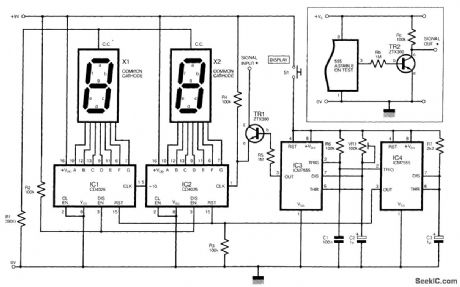
The circuit shown is a simple digital frequency meter, which indicates the frequency in hertz of an astable 555 timer. It could, perhaps, be adapted for other uses. An NPN transistor, TR2, is connected to the 555 astable to be measured, as shown in the in-set, and the output signal obtained is hooked to the main circuit via transistor TR1 collector (c). Two CMOS 7555 timers, IC3 and IC4,are wired as monostables, and these will trigger via R6 and C1 when the DISPLAY swith S1 is closed. The period of IC3 is adjustable using VR1.while IC4 times for a fraction of a second. When S1 is closed,IC4 sends a RESET signal to IC1 and IC2.which are two decade counters. each driving a seven-segment common-cathode LED display directly. IC3,the first decade counter. Monostable IC3 needs to be trimmed so that it triggers for approximately 100ms.Pressing switch S1 then allows 100ms'worth of pulses to clock up on the display, and simply multiplying the result by 10 will yield the value in hertz. It would be feasible to cascade several counters to show a higher range of frequencies. (View)
View full Circuit Diagram | Comments | Reading(10543)
1_MHz_OR_500_kHz_ELLIPTIC_LP_FILTER
Published:2009/7/13 10:07:00 Author:May

This filter uses a Linear Technology P/N LTC1560-1 to implement a switchable LP filter. (View)
View full Circuit Diagram | Comments | Reading(703)
COMMON_BASE_BLOCKING_OSCILLATOR
Published:2009/7/16 3:16:00 Author:Jessie
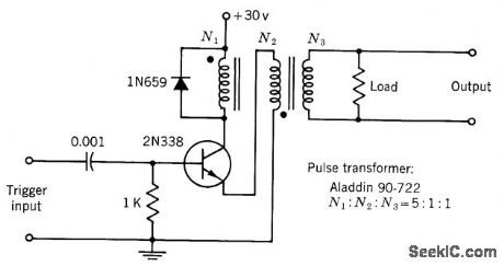
Nonsaturating-type triggered blocking oscillator is used when fast response is desired. Often used as pulse generator when waveform requirements are not critical.-Texas Instruments Inc., Transistor Circuit Design, McGraw-Hill, N.Y., 1963, p 430. (View)
View full Circuit Diagram | Comments | Reading(1088)
GATED_AMPLITUDE_RATIO_INDICATOR
Published:2009/7/16 3:16:00 Author:Jessie
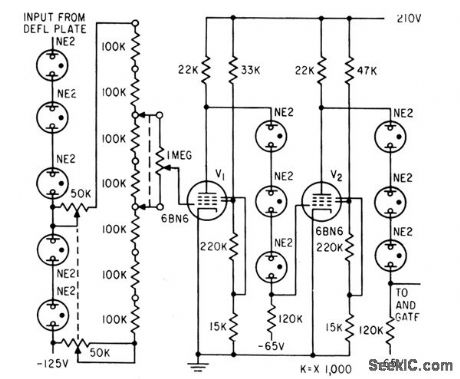
Accurately measures cylinder gas temperature as function of engine-cycle phase angle, by using amplitude discriminator to indicate ratio of two infrared radiation intensities emitted by gas at two known wavelengths. Discrimination is accomplished by amplifying 0.1% slice of radiation signal.-R. R. Bockemuehl, Gated Ratio Indicator Aids Engine Research, Electronics, 32:13, p 64-65. (View)
View full Circuit Diagram | Comments | Reading(590)
SW_RECEIVER_CW_FILTER
Published:2009/7/13 10:05:00 Author:May

The CW filter is connected between the headphone or loudspeaker socket or terminal strip of your receiver and either the headphones or an external loudspeaker. The output of the receiver should have an intpedance of 8Ω or more. As the circuit provides unity gain at pass frequencies and a low-impedance output, there should be no problems with mismatching when the filter is in use. The frequency response of the circuit peaks at approximately 800 Hz, and the -6-dB bandwidth is about 300 Hz or so. The 0-dB points occur at about 350 Hz and 2 kHz. This is sufficient to normally give a substantial reduction in adjacent-channel interference, but the response is not so narrow and peaky that using the receiver with the filter in the circuit becomes difficult, as the wanted signal tends to drift out of the passband and become lost. (View)
View full Circuit Diagram | Comments | Reading(1080)
INFRARED_POWER_MONITOR
Published:2009/7/16 3:15:00 Author:Jessie

Output of infrared signal generator is monitored by two-thermistor bolometer, low-noise nuvistor preamp, and synchronous detector driving multirange meter, all operating from two highly regulated power supplies.-A. Glaser, Signal Generator for Infrared Region, Electronics, 35:8, p 40-43. (View)
View full Circuit Diagram | Comments | Reading(627)
HIGH_PASS_LOW_PASS_FILTER
Published:2009/7/13 10:03:00 Author:May

This filter uses a Linear Technology P/N LTC1560-1 and an LT1360 to implement a high-pass/low-pass filter. (View)
View full Circuit Diagram | Comments | Reading(868)
AMATEUR_TRANSMITTER_ABSORPTIVE_FILTER
Published:2009/7/13 10:00:00 Author:May

This filter diverts harmonic energy above 30 MHz to a dummy load and dissipates it as heat instead of reflecting it back to the transmitter. The absorptive filter is based on the classic design by Weinreich and Carroll from 1968. The high-pass and low-pass sections are shielded from each other (even though they are in the same shielded box) to prevent interaction. If you want to try building this filter, wind the coils on high-powered toroids. Alternatively, you could wind an air-core coil using the nomograms in The ARRL Handbook for Radio Amateurs. (View)
View full Circuit Diagram | Comments | Reading(738)
PEAKING_FILTER_CIRCUIT
Published:2009/7/13 9:54:00 Author:May

This circuit is basically a noninverting amplifier with positive feedback. The negative feedback is to unity by a direct connection between the output terminal of the operational amplifier and the inverting (-) input. A frequency-selective RC network connects the output to the noninverting (+) input, providing some positive feedback. The center frequency is FC=1/2πR1(C1C2)1/2where FC is the center frequency in hertz, R1 is in ohms, and C1 and C2 are in farads. (View)
View full Circuit Diagram | Comments | Reading(972)
PREAMP_BOOSTS_GAIN_20_dB
Published:2009/7/16 3:12:00 Author:Jessie

Two RCA MOSFETs in cascode provide extra 20 dB of gain when used ahead of older Radio Shack AX-190 shortwave receiver. Input and output tuned circuits, gang-tuned, are part of receiver preselector. Article covers construction and tune-up.-P. J. Dujmich, Improve the AX-190 Receiver, 73 Magazine, Jan. 1978, p 106-107. (View)
View full Circuit Diagram | Comments | Reading(1117)
HEADLIGHT_DIMMER
Published:2009/7/16 3:12:00 Author:Jessie
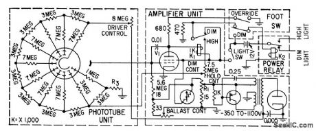
Will hold low beam setting even when approaching driver dims his headlights. Restores high beam only when light is completely removed from photocell. Street lights therefore keep system on a low beam. Used in Autronic Eye.-W. E. Bushor, Electronics and the American Automobile, Electronics, 31:47, p 73-79. (View)
View full Circuit Diagram | Comments | Reading(0)
SCS_SINGLE_PULSE_GENERATOR
Published:2009/7/16 3:11:00 Author:Jessie
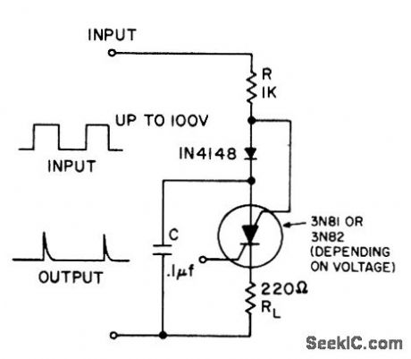
Gives one output pulse for each positive-going input. Can be used as tachometer, power loss detector, or peak detector.- Transistor Manual, Seventh Edition, General Electric Co., 1964, p 434. (View)
View full Circuit Diagram | Comments | Reading(778)
IR_WIDTH_GAGE_AMPLIFIER
Published:2009/7/16 3:11:00 Author:Jessie

Amplifies signals from two amplifiers, and combines them at second, triode of V4 for translator.Signal here consists of positive-going pulse from channel 1 and negative-going pulse from channel 2, with distance between pulses indicating strip width.-F. J. Danks, Infrared Gage Measures Hot Steel Strip Width, Electronics, 33:43, p 65-67. (View)
View full Circuit Diagram | Comments | Reading(635)
GAS_TUBE_AUTO_IGNITION
Published:2009/7/16 3:10:00 Author:Jessie
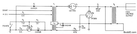
Thyratron V2 discharges C1 through spark coil T3 to provide ignition spark each time points open and magnetic field of trigger transformer T2 collapses. Field is built up in T1-T2 by power transistor Q1 when points close again,-H. P. Quinn, Gas Tubes and Transistor for Electronic Ignition, Electronics, 34:50, p 62-64. (View)
View full Circuit Diagram | Comments | Reading(1181)
| Pages:688/2234 At 20681682683684685686687688689690691692693694695696697698699700Under 20 |
Circuit Categories
power supply circuit
Amplifier Circuit
Basic Circuit
LED and Light Circuit
Sensor Circuit
Signal Processing
Electrical Equipment Circuit
Control Circuit
Remote Control Circuit
A/D-D/A Converter Circuit
Audio Circuit
Measuring and Test Circuit
Communication Circuit
Computer-Related Circuit
555 Circuit
Automotive Circuit
Repairing Circuit