LED and Light Circuit
TRICOLOR_LED_SIGN_DISPLAY
Published:2009/7/13 20:25:00 Author:May | From:SeekIC

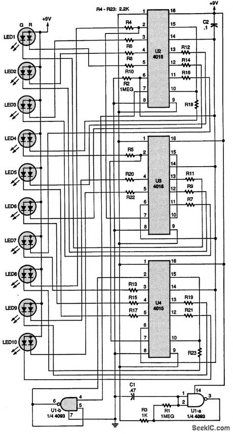
The purpose of this circuit is to light three-terminal LEDs in sequence on a small sign for a model railroad. Capacitor C2 is connected to the resets of the three 4015 shift registers, U2 to U4. When the circuit is first turned on, C2 automatically sets all the outputs to 0, thus inputting a 1 through U1-b, a section of a 4093 NAND Schmitt trigger, to the A input (pin 7) of U2. The circuit is clocked by U1-a, which is connected as an oscillator, and U1-a inverts the 0s to 1s until the first 1 is recirculated to the output of the last shift register, U4. Then the 1s become 0s and they recirculate. That all repeats as U1-a clocks the shift registers. When the first 1 is received at the first output of U2, the LED segment connected to it lights. As U1-a clocks the shift register, the LEDs connected to the other outputs sequentially light up red. After ten clock cycles, the clock skips two, and then continues lighting up the green segments of the LEDs, giving a yellowish-orange tint to them. After all the LEDs are lit, the shift register starts turning off the red LED segments. That leaves the green segments on-the third color from the LEDs. The oscillator continues to clock the green LEDs off, leaving the sign dark. After that cycle is completed, the operation repeats, giving the effect of a sign that goes from red to yellow to green to dark.
Reprinted Url Of This Article:
http://www.seekic.com/circuit_diagram/LED_and_Light_Circuit/TRICOLOR_LED_SIGN_DISPLAY.html
Print this Page | Comments | Reading(3)

Article Categories
power supply circuit
Amplifier Circuit
Basic Circuit
LED and Light Circuit
Sensor Circuit
Signal Processing
Electrical Equipment Circuit
Control Circuit
Remote Control Circuit
A/D-D/A Converter Circuit
Audio Circuit
Measuring and Test Circuit
Communication Circuit
Computer-Related Circuit
555 Circuit
Automotive Circuit
Repairing Circuit
Code: