
Circuit Diagram
Index 657
DIGITAL_LINE_SELECTING_SWITCHES
Published:2009/7/15 21:57:00 Author:Jessie
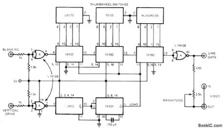
Three thumbwheel switches connected in binary mode control three 74192 counters、for selection of any desired line up to 999 in television field. Line-gate pulse injects into looped-through video for brightening selected line to make it visible on display. Circuit can also be used to determine exact number of active lines in each television field,Article describes operation in detail-H F,Stearns、Build a Thumb-wheel-Switched Television Line Selector, EDN Magazine, June 20,1976, p 124, (View)
View full Circuit Diagram | Comments | Reading(2324)
RGB_OUTPUT
Published:2009/7/15 21:55:00 Author:Jessie

Motorola MDS21 high-voltages silicon transistors serve as out put stages for red, green, and blue channels of color TV receiver, to provide video amplitude requirements for color picture tube Transistors can be driven directly by most types of chroma demodulators,-″NPN Silicon Annular High Voltage Amplifier Transistors,″Motorola, Phoenix,AZ, 1978, DS 3364. (View)
View full Circuit Diagram | Comments | Reading(2262)
AFT_SUBSYSTEM
Published:2009/7/15 21:54:00 Author:Jessie
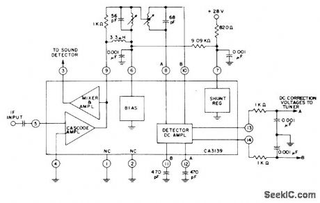
RCA CA3139 automatic fine tuning IC combined with intercarrier mixer/amplifier for color and monochrome receivers provides AFT voltage for tuner correction and amplified 4.5-MHz intercarrier sound signal for external FM sound detector of receiver. Input is taken from output of IF amplifier in receiver.- Linear Integrated Circuits and MOS/FET's, RCA Solid State Division, Somerville, NJ, 1977, p381. (View)
View full Circuit Diagram | Comments | Reading(1142)
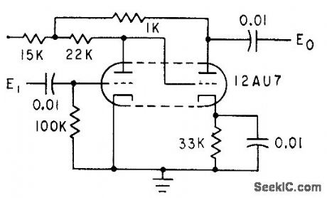
VARIABLE_DELAY_UP_TO_7_μs
Published:2009/7/15 21:52:00 Author:Jessie

Used in television broadcasting when longer delay is required than can be achieved with passive elements for composite signal.-C M, Wong、Sync –Pulse Delay Wireless World,Feb. 1977、p46. (View)
View full Circuit Diagram | Comments | Reading(1006)
IR_TRANSMITTER_FOR_TV_SOUND
Published:2009/7/15 21:51:00 Author:Jessie

Mono audio output of TV receiver is fed to infrared modulator using Intersil 8038 IC and transistor.o provide pulse-frequency-modulated infrared output that can be picked up by compact receiver built into headphones S/N ratio is 58 dB in daylight in average living room having light walls and celling, but drops to 40 dB when receiver faces away from transmitter Used in German TV receivers displayed at 1975 Berlin Exhibition.-International Radio and Television Exhibition Wireless World Nov .1975, p 521-524 and 539. (View)
View full Circuit Diagram | Comments | Reading(1871)
GATE_OPENING_100_KC_OSCILLATOR
Published:2009/7/15 21:50:00 Author:Jessie

Output voltages are taken across r-f chokes in collector circuits, for controlling number gates of crt display that creates handwritten numerals.-R L. White. Forming Handwritten like Digits on CRT display. Electronics,32:11,p138-140. (View)
View full Circuit Diagram | Comments | Reading(936)
FET_LINEAR_MODULATOR
Published:2009/7/15 21:49:00 Author:Jessie


Circuit developed for closed.-circuit industrial color television system uses linear portion of operating characteristic for 2N4931 FET to provide linear response at modulation frequencies from 1 MHz down to near zero. Article gives design equations.-G.R. Shapiro, Analog Multipliers Offer Solutions to Video Modulation Problems, EDN Magazine Sept 1,1972, p 40-41. (View)
View full Circuit Diagram | Comments | Reading(807)
PULSE_STRETCHER_WITH_ISOLATION
Published:2009/7/15 21:49:00 Author:Jessie


Motorola MOC1000 optoisolator provides safe inter-facing with digital logic while stretching input pulse. Circuit uses phototransistor of optoisolator as one of transistors in mono MVBR. With input pulse width of 3 μs, output pulse width is about 1.2 ms. - Industrial Control Engineering Bulletin, Motorola, Phoenix, AZ, 1973,EB-4. (View)
View full Circuit Diagram | Comments | Reading(963)
CHARACTER_FORMING_DOT_GENERATOR
Published:2009/7/15 21:49:00 Author:Jessie

Transistor switch, having drop of less than 50 mv when delivering 50 ma, is used in display that provides fast alphanumeric readout on crl by forming characters from series of overlapping dots.-S. C. Chao, Character Displays Using Analog Techniques, Electronics, 32:43, p 116-118. (View)
View full Circuit Diagram | Comments | Reading(724)
NANOSECOND_PULSE_DISPLAY
Published:2009/7/15 21:48:00 Author:Jessie

Magnetic-focus electrostatic-deflection beam-deflection tube permits pulse height analysis where pulse separation is of the order of microseconds.-J. Burns, Special Tubes for Nanosecond Display, Electronics, 33:49, p 82-85. (View)
View full Circuit Diagram | Comments | Reading(678)
BINARY_NEONS
Published:2009/7/15 21:46:00 Author:Jessie

Q1 and Q2 are active elements in transistor binaries, and lamps NE-A are pre-aged neons matched with respect lo firing and running voltages. Voltage at D stores information in neon lamps.-B. H. Harrison, Photoconductive Matrix Simplifies Counter Display, Electronics, 34:51, p 28-30. (View)
View full Circuit Diagram | Comments | Reading(753)
SINGLE_PULSE_SELECTOR
Published:2009/7/15 21:43:00 Author:Jessie

Circuit is used to select any desired single pulse from wavetrain continuously applied to input terminal. When enable pulse (not exceeding width of input pulse) is applied, flip-flop FF1 clocks on leading edge of next input pulse and FF2 clocks on trailing edge. Output pulse thus has same width as pulses in input wavetrain. Edge-triggering characteristics of D flip-flops prevent operation if they are enabled during input pulse; in this case, next input pulse is delivered as output.-S. J. Cormack, Pulse Catcher Uses Two ICs, EDN Magazine, Jan. 5, 1973, p 109. (View)
View full Circuit Diagram | Comments | Reading(888)
LAMP_TYPE_INDICATOR
Published:2009/7/15 21:41:00 Author:Jessie

Used as indicator in digital logic circuits. Common-emitter amplifier drives type 344 lamp rated 18 ma at 12V. Can also be used to drive electromechanical indicator having the same operating power requirements. Lamp may be remotely located.-NBS, Handbook Preferred Circuits Navy Aeronautical Electronic Equipment, Vol. II, Semiconductor Device Circuits, PSC 13 (originally PC216), p 13-2. (View)
View full Circuit Diagram | Comments | Reading(711)
GAS_TUBE_READOUT
Published:2009/7/15 21:39:00 Author:Jessie

Thyratron display tubes (Kip Memolites) remain on until next input sync pulse occurs. Static delay one. shot is then triggered, to extinguish display bulbs by dropping their plate voltage below ionization point. Bulbs ore extinguished only when new input information is to be received. Used in converting up to 13 bits from Gray code to straight binary.-R. Wasserman and W. Nutting, Solid. State Digital Code-to-Code Converter, Electronics, 32:50, p 60-63. (View)
View full Circuit Diagram | Comments | Reading(825)
1_V_HIGH_PRECISION
Published:2009/7/15 21:36:00 Author:Jessie

Drift is less than 1 mV over 20℃ temperature range, and voltage dividet reduces this to ±0.1 mV for 1.00-V reference required in 41/2 -digit meter. All three pots should be wirewound. Current of reference zener is regulated by opamp gain and zener voltage.-S. Kelley, Applications of MC1405/MC14435 in Digital Meters, Motorola, Phoenix, AZ, 1975, AN-748, p 19. (View)
View full Circuit Diagram | Comments | Reading(888)
LAMP_READOUT_INVERSION
Published:2009/7/15 21:35:00 Author:Jessie

Used if lamp output is required with switch open, or if two lamp outputs ore required (one lamp coming on for switch open and the other for switch closed). All lamps are type 39, rated 6.3V at 0.36 amp. With scr off, voltage across L1 and L2 was 0.8V with 6.3V across L3, with no visible light from L1 and L2. With scr on, there is about 6.3V across L1 and L2, with no visible output from L3.-Inversion Technique for Incandescent tamp Readouts, Electronic Circuit Design Handbook, Mactier Pub. Corp., N.Y., 1965, p 208. (View)
View full Circuit Diagram | Comments | Reading(724)
CRT_CONTROL
Published:2009/7/15 21:34:00 Author:Jessie

Takes waveforms from gates and applies them to deflection electrodes of 2-inch crt to create numeral-forming Lissajous patterns.-R. L. White, Forming Hand-written-Like Digits on CRT Display, Electronics, 32:11, p 138.140. (View)
View full Circuit Diagram | Comments | Reading(665)
CRYSTAL_VIDEO_RECEIVER_AMPLIFIER
Published:2009/7/15 23:19:00 Author:Jessie
Modified direct-coupled inverse-feedback pair of triodes handles negative pulse groups only if not too closely spaced. May be used in command guidance, radar beacon, and pulse communication applications.-R. E. Koncen, Wide-Range Multiple-Pulse Amplifier, Electronics, 33:38, p 78-81. (View)
View full Circuit Diagram | Comments | Reading(648)
10_MC_TD_MVBR
Published:2009/7/15 23:19:00 Author:Jessie

Uses two 1-ma, 0.01-ohm tunnel diodes.-I. A, Lesk, N. Holonyak, Jr., and U. S. Davidsohn, The Tunnel Diode-Circuits and Applications, Electronics, 32:48, p 60-64. (View)
View full Circuit Diagram | Comments | Reading(770)
SUPPRESSING_NOISES_UP_TO_1000_TIMES_SIGNAL_LEVEL
Published:2009/7/15 23:18:00 Author:Jessie

Improved noise limiter for airborne transceiver uses large RC time constant. Plate of detecting diode is negatively charged by a-f signal, held steady by C. For noise impulses, point A swings positively and limiter diode blocks rectified noise signal.-K. Makino and T. Yamanaka, Servo-Tuned Transceiver for Airborne VHF Communications, Electronics, 35:1, p 82-85 (View)
View full Circuit Diagram | Comments | Reading(691)
| Pages:657/2234 At 20641642643644645646647648649650651652653654655656657658659660Under 20 |
Circuit Categories
power supply circuit
Amplifier Circuit
Basic Circuit
LED and Light Circuit
Sensor Circuit
Signal Processing
Electrical Equipment Circuit
Control Circuit
Remote Control Circuit
A/D-D/A Converter Circuit
Audio Circuit
Measuring and Test Circuit
Communication Circuit
Computer-Related Circuit
555 Circuit
Automotive Circuit
Repairing Circuit