
Circuit Diagram
Index 652
10_V_MICROPOWER
Published:2009/7/15 21:13:00 Author:Jessie

Low-drift voltage reference has standby current less than 100 μA, using LM4250 opamp to convert zero-temperature-coefficient current to desired reference voltage output. Adjust Pl for low output tem-perature coefficient, and adjust P2 for exact reference desired.- Linear Applications, Vol. 2, National Semiconductor, Santa Clara, CA, 1976, LB-34. (View)
View full Circuit Diagram | Comments | Reading(740)
10_V_USING_STANDARD_CELL
Published:2009/7/15 21:12:00 Author:Jessie

Low drift and low input current of National LM121 differential amplifier provide buffering for standard cell with high accuracy. Typical long-term drift for LM121 operating at constant temperature is less than 2 μV per 1000 h. Circuit should be shielded from air currents. When power is not applied, disconnect standard cell to prevent it from discharging through internal protection diodes.- Linear Applications,Vol, 2, National Semiconductor, Santa Clara, CA, 1976, AN-79, p8. (View)
View full Circuit Diagram | Comments | Reading(836)
__15_V_AT_100_mA
Published:2009/7/15 21:11:00 Author:Jessie

Boost transistor Q1 is added inside feedback loop to amplify output current of A1 to 100 mA at scale-up reference of + 15 V from 6, 6-V value of zener. R4 and Q2 provide protection against load shorts.-W. G. Jung, IC Op-Amp Cookbook, Howard W. Sams, Indianapolis, IN, 1974, p 152-155. (View)
View full Circuit Diagram | Comments | Reading(741)
5_V_AT_75_mA
Published:2009/7/15 21:09:00 Author:Jessie

Circuit uses single pot with standard opamp to ad just output voltage and simultaneously set current of 6.2-V zener at optimum value for temperature stability. With some opamps, emitter-follower may be needed at opamp output to supply necessary zener current. Technique eliminates need for separate zener current adjustment or permits use of lower-cost zener.-K. Hanna, Single Control Adjusts Voltage Reference, EDN Magazine, June 5, 1976, p 117. (View)
View full Circuit Diagram | Comments | Reading(785)
SONAR_TIMER_AND_CRO
Published:2009/7/15 21:08:00 Author:Jessie

Timing functions, induding display, are derived from cam op erated switches driven by synchronous motor. Thyrcmon V6 discharges sweep capacitor. Leading edge of received echo is cdigned by delay control with crt reference Iine, and delay time in millisec is read di-rectly from dial.-L. H. Dulberger, Sonar to Survey Arctic Ocean Shelf Transmits Through Ice and Water, Electronics, 34;31, p 44-45. (View)
View full Circuit Diagram | Comments | Reading(866)
SELF_STABILIZING_ZENER
Published:2009/7/15 21:08:00 Author:Jessie

Current through 7.5-mA zener CR1 is independent of supply volt-age, which may be as low as 10V. Negative reference is 1.1 times zener rating, or -6.8 V for zenel shown. Article describes circuit operation and gives design equations.-L. Accardi, Super-Stable Reference-Voltage Source, EDN/EEE Magazine, Oct. 1, 1971, p 41-42. (View)
View full Circuit Diagram | Comments | Reading(758)
CAMCORDER_BATTERY_PROTECTOR
Published:2009/7/14 2:27:00 Author:May

Many camcorder enthusiasts use their spare battery for powering video lights. Many such lights give no indication when the battery has gone flat. This can be avoided by the use of this protection circuit. When it gets switched on, the potential across C1 is zero, so that T2 is cut off, the relay is inactive, and the indicator lamp lights. As long as the battery voltage remains above a certain level, T1 is on and holds the base of T2 at earth potential. In this state, only a small current is drawn. When the battery voltage is no longer higher than the sum of the zener voltage, the potential set by divider R2-P1, and the drop across the base-emitter junction of T1, this transistor is cut off, whereupon C 1 is charged via R2. When the potential across C1 has risen to a value high enough for T2 to be switched on, the relay is energized, and its contact disconnects the lamp from the battery. Because the current drain (≤70 rnA) is then determined almost entirely by the relay, it is essential to remove, or disconnect, the battery from the light unit. The switch-off voltage level, set with P1, should be about 1 V per battery cell. (View)
View full Circuit Diagram | Comments | Reading(707)
1O_STATE_RING_COUNTER
Published:2009/7/15 21:06:00 Author:Jessie

Flip-fiop drives ring-of-five stage that in tum drives diode malrix which trcnslales each slored deci-mal number to electroluminescent display segment code.-R. C. Lyman and C. I. Jones, Eleclroluminescenf Panels for Aulomatic Displays, Electronics, 32:28, p 44-47. (View)
View full Circuit Diagram | Comments | Reading(788)
BATTERY_TESTER
Published:2009/7/14 2:22:00 Author:May

Although deceptively simple, this battery tester can help you weed out marginal cells that might otherwise test good. Six incandescent lamps, chosen for their voltage and current ratings, are selected as a load for the battery under test. The meter (M1) and the lamp's brightness will give a good indication of a battery's output capacity. In addition, because the inrush current that occurs when the lamp is first connected across the battery is much higher than the rated operation value, the circuit makes it easy to spot marginal cells. To use the circuit, connect a battery and observe the measured voltage on M1. Then close the switch that corresponds to the meter's reading and/or the battery's rated voltage and observe the brightness of the appropriate lamp. Be careful to select the right lamp for testing. Never test using a lamp whose voltage rating is more than 30 percent lower than the battery's rating. Otherwise, damage to the lamp could result if the battery under test is good.
(View)
View full Circuit Diagram | Comments | Reading(0)
DIFFERENTIAL_DISCRIMINATOR
Published:2009/7/15 21:05:00 Author:Jessie
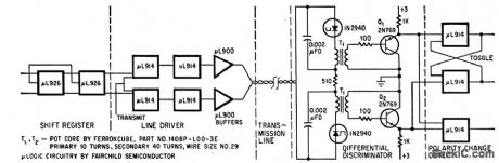
Tunnel diodes serve as current level detectors, allowing detection of serial bit information while providing common-mode rejection of noise. Used in system for transmitting phase-moduulated digital data over telephone line. Original pulse waveforms are restored by diodes.-F. Salter, Differential Discriminator Rejects Common-Mode Noise.Electronics.39:15,p101-102. (View)
View full Circuit Diagram | Comments | Reading(451)
±7_V_REFERENCE
Published:2009/7/15 22:13:00 Author:Jessie

Developed for analog applications requiring dual-polarity references. Both voltages are generated from single μA723 IC voltage regulator chip. Chief requirement is keeping inputs and outputs within dynamic range of amplifier, which is +2 to +9 V; this is done by shifting output voltage level upward with zener D1 and shifting input error voltage with divider R1-R2. Changing ratio of R3 to R4 changes negative reference value.-D. Weigand, Dual 7V Reference Developed from a Single μA723, EDN Magazine, Nov. 1, 1972, p 47. (View)
View full Circuit Diagram | Comments | Reading(786)
_66_V_AT_5_mA
Published:2009/7/15 21:33:00 Author:Jessie

Half of 1558 dual opamp is used as buffer for basic opamp-zener voltage reference to raise output current and lower output impedance-W. G. Jung, IC Op-Amp Cookbook, Howard W Sams, Indianapolis, IN, 1974, p 150-151. (View)
View full Circuit Diagram | Comments | Reading(850)
FOUR_ELECTRODE_NEON
Published:2009/7/15 21:32:00 Author:Jessie

On-off indicator for transistorized flip-flop operates on voltage differential of 6V.-A. Erikson, French Components Gaiting Smaller, Electronics, 34:11, p 24-25. (View)
View full Circuit Diagram | Comments | Reading(618)
_66_V_WITH_741_OPAMP
Published:2009/7/15 21:32:00 Author:Jessie

Reference output of -6.6 V, determined by breakdown voltage of zener, is scaled to more negative level at output of A1. If 1558 dual opamp is used in place of 741, other section can be connected to zener as buffer that raises output current to 5 mA and lowers output impedance.-W. G. Jung, IC 0p-Amp Cookbook, Howard W. Sams, Indianapolis, IN, 1974, p 151. (View)
View full Circuit Diagram | Comments | Reading(1192)
VARIABLE_25_10_V
Published:2009/7/15 21:31:00 Author:Jessie

General-purpose opamp and tenet, operating from single 15 V supply, serve as stable buffered voltage reference source that is readily adapted to wide range of output voltages and currents. R4 applies some fraction of zener's 2.5 V to opamp, which amplifies it by factor of 4 to give 2.5 to 10 V output. Output current rating depends on opamp and is about 10 mA for general-purpose types. 759 will handle up to 350 mA, and other devices can be buffered with NPN emitter-follower stage. For greater output range, use higher supply voltage and ad just R2 accordingly. R3 should be chosen to maintain about 1 mA in zener.-W. Jung, An IC Op Amp Update, Ham Radio, March 1978, p 62-69. (View)
View full Circuit Diagram | Comments | Reading(1654)
CCTV_DISPLAYS_VOLTAGES_AS_VOLTAGES_BAR_GRAPHS
Published:2009/7/15 21:25:00 Author:Jessie
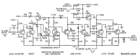
No change is necessary in closed-circuit television monitor. Switch gives choice of bar graph or picture display. Horizontal lines can be electronically positioned on screen as go and no go limits. Display con version system has counter that commutates up to 20 low-frequency analog voltages on to common bus feeding comparator input shown.-D. Cohen. Converter Produces Television Bar Display. Electronics.34:44,p45-47. (View)
View full Circuit Diagram | Comments | Reading(732)
PULSE_COINCIDENCE_CONTROL
Published:2009/7/15 21:24:00 Author:Jessie

Coincidence of incoming code with reference pulse causes cold-cathode code tubes to fire in accordance with binary number present, for driving display panel containing eight sections each having 30 miniature fucrescent lamps.-T. S. Pick and A. Roadman, Photoelectric Scanners Control Bus traffic, Electronics, 32:28, p 50-,51. (View)
View full Circuit Diagram | Comments | Reading(663)
10_V_HIGH_PRECISION
Published:2009/7/15 21:24:00 Author:Jessie

Use of LM399 thermally stabilized subsurface zener in state-of-the-art reference circuit keeps temperature error well under 2 PPM/℃ over temperature range of 0 to 70℃. Article gives design equation and covers procedures for optimizing stability and minimizing power-supply rejection-ratio errors.-W. G. Jung, Precision Reference Source Features Minimum Errors, EDN Magazine, Aug. 5, 1976, p 80 and 82.
(View)
View full Circuit Diagram | Comments | Reading(2621)
KILOVOLT_PULSES
Published:2009/7/15 21:23:00 Author:Jessie

Simple circuit generates 1.5-kV pulses at fixed rate equal to line frequency. Used to drive small piezoelectric transducers for sound velocity measurements. Absence of power transformer minimizes cost, size, and weight. During half of AC cycle, C1 charges. During other half, C1 discharges through Q2 into primaries T1, T2, and T3 to provide output pulse. R3, C2, D5, D4, and T4 provide trigger pulse for turning on Q2. Shunt regulator formed by D2, D3, R2, Q1, and L1 clamps voltage across C1 at 130 V to ensure constant amplitude of output pulses.-S. Anderson, Portable Generator Produces Kilovolt Pulses, EDN Magazine, Oct. 20, 1977, p 102. (View)
View full Circuit Diagram | Comments | Reading(783)
BUFFERED_10_V
Published:2009/7/15 21:23:00 Author:Jessie

Reference voltage developed by National LM199 temperature-stabilized IC is 6.95 V with very low temperature drift and excellent long-term stability. LH0044 precision low-noise opamp is used to scale and buffer reference to give required output of 10 V. Regulation of 15-V supply need be only about 1%.- Linear Applications, Vol. 2, National Semiconductor, Santa Clara, CA, 1976, AN-161, p 5. (View)
View full Circuit Diagram | Comments | Reading(848)
| Pages:652/2234 At 20641642643644645646647648649650651652653654655656657658659660Under 20 |
Circuit Categories
power supply circuit
Amplifier Circuit
Basic Circuit
LED and Light Circuit
Sensor Circuit
Signal Processing
Electrical Equipment Circuit
Control Circuit
Remote Control Circuit
A/D-D/A Converter Circuit
Audio Circuit
Measuring and Test Circuit
Communication Circuit
Computer-Related Circuit
555 Circuit
Automotive Circuit
Repairing Circuit