
Circuit Diagram
Index 658
PRF_GENERATOR_1
Published:2009/7/15 23:18:00 Author:Jessie

Used as repetition rate generator in airborne radar. Gives greater frequency stability than blocking oscillator and greater economy of components than Wien-bridge oscillator.-NBS, Handbook Preferred Circuits Navy Aeronautical Electronic Equipment, Vol. 1, Electron Tube Circuits, 1963, p N5-1. (View)
View full Circuit Diagram | Comments | Reading(875)
ADJUSTABLE_CURRENT_LIMITER
Published:2009/7/15 23:17:00 Author:Jessie

Q1 conducts when current exceeds limiting value deter-mined by setting of R3, turning on Q2 and in effect grounding base of Q6, to prevent significant current flow in Q3. Circuit resets automatically when overload is removed.-P. Galluzzi, Adjustable Current Limiter for Regulated Power Supply, Electronics, 395, p 107. (View)
View full Circuit Diagram | Comments | Reading(3188)
NONINVERTING_AMPLIFIER
Published:2009/7/15 23:17:00 Author:Jessie

Increases amplitude of 1-pps pulses and decreases rise and fall times. For adjustable output amplitude, R5 can be potentiometer.-R. L. Sazpansky, Non-Inverting Pulse Amplifier Uses One Power Supply, EEE, 14:1, p 63. (View)
View full Circuit Diagram | Comments | Reading(0)
RELAY_ONLY_MVBR
Published:2009/7/15 23:16:00 Author:Jessie

Consumes power only during switching. Can provide bistable, monostable, or astable operation at frequencies from a few operations per second to a few operations per hour.-R. L. Ives, Multivibrator for Low Frequencies Uses Relays, Electronics, 34:32, p 166-169. (View)
View full Circuit Diagram | Comments | Reading(680)
80_DB_DYNAMIC_RANGE_AT_8_MC
Published:2009/7/15 23:16:00 Author:Jessie

Uses five identical cascaded stages with filter to re store sinusoidal waveform. Phase-shill variations are only 10. Limits input signal by collector current cutoff only. Used in multichannel-tracking receiving system.-S. P. VV.Stranddorf, High-Frequency limiter Amplifier Solves Phase-Shift Problems, Electronics, 35:46, p 44-45. (View)
View full Circuit Diagram | Comments | Reading(641)
LINEAR_VOLTAGE_FREQUENCY_CONVERTER
Published:2009/7/15 23:16:00 Author:Jessie

Addilion of two transistors to conventional astable mvbr gives constant-current charging of cross-coupling capacitors C1 and C2. Output frequency then varies linearly from 2,000 to 7,000 cps as d-c input rises from 0 to 5 V.-R. W. Biddlecomb, Latest Multivibrator Improvement: Linear Voltage-to-Frequency Converter, Electronics, 36:17, p 64-65. (View)
View full Circuit Diagram | Comments | Reading(703)
FAST_ACTING_NONLINEAR_FEEDBACK
Published:2009/7/15 23:15:00 Author:Jessie
Keeps output variation within 8 db for input level variation of 38 db. Amplifies 100-kc square waves and limits output amplitude without introducing phase distortion, Amplilcation is determined by input level. For signals below 5 my peak, 38 db of gain is provided, auto. matically diminishing for higher-level input signals. With 400.mY peak input, gain is slightly over unity.-L. H. Dulberger, Pulse Amplifer with Nonlinear Feedback, Electronics, 31:45, p 86-87. (View)
View full Circuit Diagram | Comments | Reading(644)
DIODE_PAIRS
Published:2009/7/15 23:15:00 Author:Jessie

High-speed silicon diode pairs in two-stage limiter for telemetry, measuring, aft systems, and f-m systems give 5% linearity over 6-Mc bandwidth. Associated discriminator uses two single poles resistively coupled to driving tube.-High-Speed Diodes Make Limiting Smooth, Electronics, 35:27, p80. (View)
View full Circuit Diagram | Comments | Reading(768)
FAST_RISE_TIME
Published:2009/7/15 23:14:00 Author:Jessie

Achieved by precise bias control of Q2 without introducing pclrclsifics in input signal Iine. Gives high gain-band-width product as pulse amplifier.-D. D. McLeod, Bias Control and Low Parasitics Shorten Amplifier Rise Time, Elecnonics, 39:2, p 73-74. (View)
View full Circuit Diagram | Comments | Reading(871)
MONO_DESIGN
Published:2009/7/15 23:20:00 Author:Jessie

Simplified equations are given for designing emitter-coupled monostable mvbr. With 20-V supply, component values for use with 2N388 transistors to provide 25-microsec pulse width, for E1=4 V and E2 =7 V are RE=1K, RL2=1,800 ohms, RL1 = 3,900 ohms, R1 = 56,000 units, R2=27,000 ohms, and C1= 620 pf.-L. I. Kleinberg, Designing Emitter-Coupled Monostable Multivibrators, Electronics, 34:39, p 86. (View)
View full Circuit Diagram | Comments | Reading(1070)
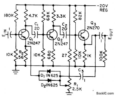
PULSE_POWER_AMPLIFIER
Published:2009/7/15 23:20:00 Author:Jessie

Operates as inverting power amplifier for either pulses or levels. Input levels are -6.2 v at 3.1 ma for logical 1 and -0.15 v for logical 0. Pulse polarity may be positive or negative 6 v. Third transistor is used for handling up to 40 flip-flop or gate loads. Two transistors will handle up to 12 such loads.-NBC, Hand-book Preferred Circuits Navy Aeronautical Electronic Equipment, Vol. II, Semiconductor Device Circuits, PSC 12 (originally PC 215), p 12-2. (View)
View full Circuit Diagram | Comments | Reading(1300)
PREFERRED_VIDEO_LIMITER
Published:2009/7/15 23:20:00 Author:Jessie
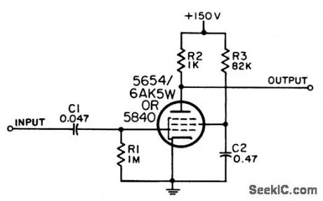
Used to amplify and limit low-level video signals. Capable of handling very fast rise times. Maximum duty factor is 4%. Limiting level is within 35% of 4.8 V, depending on variations in tube and components.-NBS, Handbook Preferred Circuits Navy Aeroncautical Electronic Equipment, Vol. 1, Electron Tube Circuits, 1963, PC 21, p 21-2. (View)
View full Circuit Diagram | Comments | Reading(945)
GATED_DELAY
Published:2009/7/16 1:47:00 Author:Jessie

Negative output dock pulses of 256-pctmmeter microwave system checker are applied to gaing diode D1, which ordinarily blocks signal to delay mvbr. During eighth pulse of code train, diodes D2-D3-D4 receive negative voltage from their binary outputs and make D1 trigger mvbr through D5. At end of mvbr delay, damp is removed until eight more pulses arrive.-J. B. Bullock, Pulse-Coded Fault Alarm in Microwave Systems, Electronics, 33:1, p 82-84. (View)
View full Circuit Diagram | Comments | Reading(586)
LINEAR_PULSE_AMPLIFIER
Published:2009/7/15 22:44:00 Author:Jessie
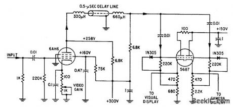
Simple linear amplifier drives two cathode followers through delay line. One output goes to one crt grid for intensity modulation. Other output goes to horizontal plates of another crt bar presentation.-M.T. Nador, Microsecond Sampler Handles 126 Channels, Electronics, 32:4, p 36-39. (View)
View full Circuit Diagram | Comments | Reading(860)
AM_SUPERHET_SUBSYSTEM
Published:2009/7/15 22:44:00 Author:Jessie


RCA CA3123E provides all active elements needed up to audio volume control Table gives values of components for tuned circuits Operates from single 12-V supply, making subsystem particularly suitable for auto radios. IF value is 262 kHz. 1-MHz signal generator shown in input circuit is used only for initial tuning.- Linear Integrated Circuits and MOS/FET's , RCA Solid State Division, Somerville, NJ 1977, p 361-362.
(View)
View full Circuit Diagram | Comments | Reading(882)
4_W_AT_150_V_FROM_FLASHLIGHT_CELL
Published:2009/7/15 22:44:00 Author:Jessie

Portable supply operates at 80% efficiency through use of rapid-switching transistors.-H. F. Weber, Low Voltage Inverter Features High Frequency Operation with High Efficiency, Motorola Application Note AN.174, Feb. 1966. (View)
View full Circuit Diagram | Comments | Reading(658)
LIGHT_ALARM
Published:2009/7/15 22:43:00 Author:Jessie

The circuit is activated if Tr1 is switched on by a suitable base current and voltage. The voltage and current available aJt the base of Tr1 are dependent on two main factors: the resistance provided by R4 and the setting of control VR1. If VR1 is set at maximum value, photocell PCC1 needs to have a resistance of about 10,000 Ω to bias Tr1 into conduction and activate the audio alarm circuit, of which IC1 is a primary part. Fixed resistor R4 has been used across the base-emitter terminals of the switching transistor so that the sensitivity of the circuit is preset. R4 can be raised somewhat in value if increased sensitivity is required. The audio-alarm generator uses an LM380N (IC1) in a simple au-dio-oscillator circuit, and drives high-impedance loudspeaker LS1 via coupling capacitor C3. Pro-vided the losses through this coupling are less than the voltage gain provided by the amplifier, this will give sufficient positive feedback to sustain oscillation. The values for R1, R2, and C2 shown in the circuit diagram give considerably more feedback than is needed to just sustain oscillations, and the circuit oscillates strongly, producing a square-wave output at a frequency in the region of 1 kHz (1000 Hz). (View)
View full Circuit Diagram | Comments | Reading(1204)
NEGATIVERESISTANCE_DIODE
Published:2009/7/15 22:43:00 Author:Jessie

Input pulses as low as 0.01 ma are sufficient to hold negcttive-resistcmce diode in high-current region. When pulse is shut off, diode current decays to low.current state. Amplifier tends to square up input pulses.-A. P, Schmid, Jr., Negative4tesistcmce Diode Handles High Power, Electronics, 34:34, p 44-46. (View)
View full Circuit Diagram | Comments | Reading(646)
INVERTER_WITH_CAPACITOR_TURNOFF
Published:2009/7/15 22:43:00 Author:Jessie

Load power factor variations do not affect turnoff time. Varying trigger rate of Q2 varies power delivered to R1. Trigger rate can be adjusted automatically for load regulation.-D. V. Jones, Turn-Off Circuits for Controlled Recliners, Electronics, 33:32, p 52-55. (View)
View full Circuit Diagram | Comments | Reading(594)
CURRENT_DRIVER
Published:2009/7/15 23:24:00 Author:Jessie
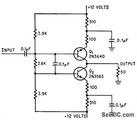
Provides fast rise time and equal-amplitude positive and negative output pulses (equal-polarity drive) for 50-ohm loud. -E. J. Kennedy, Fast-Pulse Amplifer Drives 50-Ohm Load, Electronics, 39:2, p 76. (View)
View full Circuit Diagram | Comments | Reading(937)
| Pages:658/2234 At 20641642643644645646647648649650651652653654655656657658659660Under 20 |
Circuit Categories
power supply circuit
Amplifier Circuit
Basic Circuit
LED and Light Circuit
Sensor Circuit
Signal Processing
Electrical Equipment Circuit
Control Circuit
Remote Control Circuit
A/D-D/A Converter Circuit
Audio Circuit
Measuring and Test Circuit
Communication Circuit
Computer-Related Circuit
555 Circuit
Automotive Circuit
Repairing Circuit