
Circuit Diagram
Index 641
PROGRAMMABLE_GAIN__OPAMP
Published:2009/7/14 3:43:00 Author:May
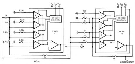

Cascading two HA-2400 digitally programmed amplifiers, each combining functions of analog switches and high-performance opamps on single IC chip, gives 16 different programmable gains in unit steps. Article gives truth table showing total gain obtained for 16 combinations of 0 and 1 on control lines D10, D11, D20, and D21. Enable lines are normally at 1, and E2 is made0 only when total gain must be zero. Applications include digital AGC and digital control of servo-systems and level detectors.-J. A. Connelly, N.C. Currie, and D. S. Bonnet, Op Amp Has 16-Step Digital Gain Control, EDN Magazine, May 5, 1974, p 75 and 77. (View)
View full Circuit Diagram | Comments | Reading(744)
PERCUSSION_OR_ELECTRONIC_MUSIC
Published:2009/7/14 3:43:00 Author:May

Provides congruent envelope shaping and coincident percussive envelope shaping of synthesized program material. One input accepts control signal, while other accepts material requiring envelope shaping.-H. Bode, Sound Synthesizer Creates New Musical Effects, Electronics, 34:48, p 33-37. (View)
View full Circuit Diagram | Comments | Reading(742)
80_METER_VFO
Published:2009/7/14 3:42:00 Author:May

Used in place of crystal-con- trolled oscillator in low-power (QRP) amateur -transmitter. Tuning range is 1750-1875 kHz in 160-meter band. Colpitts oscillator uses JFET Q5 with series-tuned tank for good stability. Q6 provides isolation between oscillator and push-push class C doubler amplifier stage. Doubling gives desired 80-meter output.-D. DeMaw and J. Rusgrove, Learning to Work with Semicon-ductors, QST, Oct. 1975, p 38-42. (View)
View full Circuit Diagram | Comments | Reading(2171)
ORGAN_PEDAL_GENERATOR
Published:2009/7/14 3:42:00 Author:May

Shaper V2 yields sawtooth wave with steeper flyback than from neon oscillator. Output of V2 feeds bistable mvbr V1 which changes state with each input trigger. Bistable output at V1A is half the input frequency (one octave lower), so 16-ft pedal tones are produced without low-frequency divider stage for each tone generator.-R. H. Dorf, Electronic Organ Uses Neon Tone Generators, Electronics, 31:35, p 36-41. (View)
View full Circuit Diagram | Comments | Reading(744)
NEON_TONE_GENERATOR
Published:2009/7/14 3:41:00 Author:May

Each of 12 organ tone generators has four pairs of neon tubes in series, each pair shunted by two series capacitors. With signal taken from common point between capacitors, sufficient insolation exists to prevent feedback and spurious tones in output. Master oscillator provides initial sync for neon-lamp divider chain. Article gives capacitor values for each musical note.-R. H. Dorf, Electronic Organ Uses Neon Tone Generators, Electronics, 31:35, p 36-41. (View)
View full Circuit Diagram | Comments | Reading(983)
ORGAN_VOICING_PANEL
Published:2009/7/14 3:41:00 Author:May

Contains formant filters that transform sawtooth generator signals into waveforms of various instruments. 19 different tone colors or timbres are available, ranging from sharp strings and reeds to bland flutes and pipelike diapasons. Filters are interlocked to produce composite effects.-R. H. Dorf, Electronic Organ Uses Neon Tone Generators, Electronics, 31 ;35,p 36-41. (View)
View full Circuit Diagram | Comments | Reading(1625)
BILATERAL_CURRENT_SOURCE
Published:2009/7/14 3:41:00 Author:May

Output current through load is constant within 2% of value related to input voltage and resistor values, regardless of variations in load from 10 to 2000 ohms. Circuit is built around Precision Monolithics OP-08 opamp.- Precision Low Input Current Op Amp, Precision Monolithics, Santa Clara, CA, 1978, OP-08, p 7. (View)
View full Circuit Diagram | Comments | Reading(2224)
35_W_CLASS_D_ON_40_80_OR_160_m
Published:2009/7/14 3:41:00 Author:May

Can be used on any of three bands by changing values as set forth in parts table. Article gives circuit design procedure in detail. Power gain is about 27 dB. Almost any type of RF amplifier providing about 100 mW can be used as driver. VS is 25 V or less, and VCC, is 28 V.-F. H. Raab, High-Efficiency RF Power Amplifiers, Ham Radio, 0ct. 1974, p 8-29. (View)
View full Circuit Diagram | Comments | Reading(795)
PUSH_PULL_OUTPUT
Published:2009/7/14 3:41:00 Author:May

Transformer-coupled push-pull output for SG3524 fixed-frequency pulse-duration- modulated switching regulator gives output flexibility, allowing for multiple outputs and wide range of output voltages. Each output transistor operates alternately at half of switching frequency. Switching regulator applies voltage alternately to opposite ends of transformer primary, making transformer perform as if it had AC input. TIP101A rectifier then provides desired 5-VDC output at 5A.-J. Spencer, Monolithic Switching Regulators-They Fit Today's Power-Supply Needs, EDN Magazine, Sept. 5, 1977, p 117-121. (View)
View full Circuit Diagram | Comments | Reading(1305)
2_KC_SCR_INVERTER
Published:2009/7/15 5:03:00 Author:Jessie

Circuit shows parallel inverter, but unijunction relaxation oscillators Q1and Q2 could also trigger series inverter, giving symmetrical operation. Q1 operates at twice the frequency of Q2.-D. V. Jones, Turn-Off Circuits for Controlled Rectifiers, Electronics, 33:32, p 52-55. (View)
View full Circuit Diagram | Comments | Reading(1321)
400_V_OUTPUT_SWING_WITH_TRANSISTORS
Published:2009/7/15 5:03:00 Author:Jessie
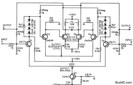
Direct-coupled differential voltage amplifier gives gain of 100 as low-frequency oscilloscope amplifier. Drift is less than 1V over normal room temperature range. Output quiescent level is 0V to ground, peak noise level is 3V, and bandwidth is 5 kc. Amplifier is not damaged by shorted output, overdrive, or supply voltages applied in any sequence.-C. L. Benson, 400,Volt Output Transistor Amplifier, EEE, 14:8, p 168. (View)
View full Circuit Diagram | Comments | Reading(783)
TELEPHONE_RING_FLASHER
Published:2009/7/14 3:41:00 Author:May

When the phone rings, the flasher turns on and off, causing photocell R1 to conduct. Relay RY1 is then energized, which completes the circuit between the light and the ac line. Thus, the light flashes in step with the rings. (View)
View full Circuit Diagram | Comments | Reading(1160)
ORGAN_SWELL_SHOE
Published:2009/7/14 3:40:00 Author:May

Uses capacitive volume control C1 to replace expensive industrial-type potentiometer. Operation of swell shoe varies value of C2 which consists of two hinged metal plates. C1 is series leg of capacitive voltage divider, shunt leg of which is dynamic capacitance of about 0.02 mfd across tube grid due to capacitive feedback from plate through C2. Attenuation range is great, and noise and hum cue negligible.-R. H. Dorf, Electronic Organ Uses Neon Tone Generators, Electronics, 31:35, p 36-41. (View)
View full Circuit Diagram | Comments | Reading(598)
D_C_FROM_F_M
Published:2009/7/15 3:55:00 Author:Jessie

Mean d-c level, directly proportional to number of pulses per unit time, is read on meter for f-m data recorded on magnetic tape.-K. R. Whittington, Simple F-M Demodulator for Audio Frequencies, Electronics, 35:48, p 89. (View)
View full Circuit Diagram | Comments | Reading(662)
PROGRAMMABLE_ASTABLE
Published:2009/7/14 3:40:00 Author:May

Square-wave output frequency of Exar XR-2240 programmable timer/counter is made digitally programmable by use of 4051 CMOS multiplexer having three-line channel-select control ABC, Lines select one of eight possible switching paths by binary combination. When all three inputs are zero, highest of eight basic output frequencies of 2240 is obtained, as shown in truth table. Circuit will yield outputs with periods of 1, 2, 4, 8, 16, 32, 64, and 128 s. -W. G. Jung, IC Timer Cookbook, Howard W. Sams, Indianapolis, IN, 1977, p 123-125. (View)
View full Circuit Diagram | Comments | Reading(0)
0_2_V_DVM
Published:2009/7/15 3:53:00 Author:Jessie

Uses three Motorola digital voltmeter ICs preceded by opamp having 10-meg-ohm input impedance, driving Hewlett-Packard HP5082 multiplexed digital display, with LED serving as decimal point. Input leads must be reversed to read negative voltages. Article gives construction and calibration details. Errata: move C3 upper connection to pin 9 of IC2, and transpose connections to pins 1 and 2 of IC3.-G. McClellan, DVMs Get Simpler and Simpler,73 Magazine, Feb. 1977, p 60-63.
(View)
View full Circuit Diagram | Comments | Reading(1671)
DIATHERMY_FREQUENCY_MONITOR_AND_CONTROL
Published:2009/7/14 3:40:00 Author:May

Monitor circuit stops 27.12-Mc oscillator and sounds buzzer when frequency drifts beyond legal limits established by FCC.-J. Markus and V. Zeluff, Handbook of Industrial Electronic Control Circuits, McGraw-Hill, N.Y., 1956, p 100. (View)
View full Circuit Diagram | Comments | Reading(760)
VIDEO_MODULATOR
Published:2009/7/15 3:52:00 Author:Jessie

Developed for use between solid-state TV camera and VHF Engineering TX-432B crystal-controlled solid-state exciter to give simple amateur TV transmitter, For tube-type cameras, add 1N914 or other small-signal silicon diodes in series with input until modulator provides proper video swing Article gives construction details,-R E Taggart, Interested in Television, 73 Magazine,Oct 1977,p 164-174. (View)
View full Circuit Diagram | Comments | Reading(0)
BIDIRECTIONAL_MULTIDECADE_COUNTER
Published:2009/7/14 1:51:00 Author:May

Single sign-determining circuit of input to tens stage provides gating signals for every decade, to handle rapid reversal of count direction.-L. C. Burnett, Reversible Decade Counter, Electronics, 35:9, p 46. (View)
View full Circuit Diagram | Comments | Reading(809)
DVM_POLARITY_INDICATOR
Published:2009/7/15 3:51:00 Author:Jessie

Designed for use in low-cost digital voltmeters. With input polarity as indicated, arrows on connections indicate direction of current flow. When NPN Q1 is on, LED 2 will be on; with PNP Q2 on, LED 1 will be on. Darlingtons Q1-Q2 draw very little current, so choice of type is not critical. AC supply is usually available in lab but can be replaced by internal clock of DVM driving small transformer to give required floating AC source, A, B, C, and D identify nodes of bridge.-R. A. Snyder, Polarity Indicator Minimizes Parts Count, EDN Magazine, Feb. 20, 1977, p 121. (View)
View full Circuit Diagram | Comments | Reading(804)
| Pages:641/2234 At 20641642643644645646647648649650651652653654655656657658659660Under 20 |
Circuit Categories
power supply circuit
Amplifier Circuit
Basic Circuit
LED and Light Circuit
Sensor Circuit
Signal Processing
Electrical Equipment Circuit
Control Circuit
Remote Control Circuit
A/D-D/A Converter Circuit
Audio Circuit
Measuring and Test Circuit
Communication Circuit
Computer-Related Circuit
555 Circuit
Automotive Circuit
Repairing Circuit