About SeekIC | Services | Payment | Advertisements service | Contact Us | Links
© 2008-2012 SeekIC.com Corp.All Rights Reserved.

Published:2009/7/15 3:50:00 Author:Jessie


Uses Siliconix LD111 IC analog processor section of digital voltmeterIC pair to combine desirable features of digital voltmeter with signal-averaging advantages of ordinary meter. Input range covered is 10 mV to 3 V, with resistive divider being required for larger input voltage. Differential inputs each have 1-gigohm input impedance. Circuit requires only two 9-V batteries. Article describes operation in detail.-B. Harvey, Digital Voltmeter IC Drives Analog Meter, EDN Magazine, June 20, 1977, p 113. (View)
View full Circuit Diagram | Comments | Reading(877)
Published:2009/7/14 1:50:00 Author:May

Changing value of L2 changes scale factor in range of 2 to 8. Circuit operates to 10 Mc at scale of 5.-C.A.Budde. One-Stage Scale Needs No Complex Feedback, Electroics.36:39,p32-33 (View)
View full Circuit Diagram | Comments | Reading(816)
Published:2009/7/15 3:49:00 Author:Jessie

Operates over range of 1kc to 20 Mc without need for tuning. In phase-locking applications, both inputs may be single-ended. Output voltage is proportional to phase difference between input signals.-H. F. Strenglein, Phase Demodulator Needs no Tuning, Electronics, 38:20, p 99. (View)
View full Circuit Diagram | Comments | Reading(850)
Published:2009/7/15 3:49:00 Author:Jessie

By setting DC reference input of 710 comparator at 0.15 CDC.only horizontal sync pulses are extracted from composite black-negative video signal to appear at comparator output Setting reference level at 0.35 VDC gives only blanking pulses at output.-R,G, Groom IC Comparator Separates Sync Pulses EDN Magazine, Sept 15.1970.p 53-54. (View)
View full Circuit Diagram | Comments | Reading(760)
Published:2009/7/15 3:48:00 Author:Jessie

Used in iceberg-detecting microwave radiometer. Faraday rotational ferrite switch alternately feeds calibrating noise source and ocean or iceberg signal through video amplifier to double-bridge demodulator. Output is d-c voltage proportional to change in antenna temperature, positive for warm signals from iceberg and negative for apparently colder sea water. Mvbr (125 cps) supplies reference voltage and ferrite drive signal.-T. V. Seling and D. K. Nance, Sensitive Microwave Radiometer Detects Small Icebergs, Electronics, 34:19, p 72-75. (View)
View full Circuit Diagram | Comments | Reading(905)
Published:2009/7/15 3:43:00 Author:Jessie

Detects weak low-frequency signals in high-noise background, with output indicating presence and phase shift of signals received at dual inputs. Accuracy is within 1% for inputs of 1 to 500 cps.-B. M. Rosenheck, Detecting Signals by Polarity Coincidence, Electronics, 33:5, p 67-69. (View)
View full Circuit Diagram | Comments | Reading(937)
Published:2009/7/15 3:42:00 Author:Jessie

Input pulse turns off silicon controlled switch, which triggers after delay of approximately RC.- Transistor Manual, Seventh Edition, General Electric Co. 1964, p 435. (View)
View full Circuit Diagram | Comments | Reading(522)
Published:2009/7/15 3:40:00 Author:Jessie

Voltage controlled audio oscillator A2 serves for rough measurements of up to 10 VDC, allowing user to keep eyes on test probe during troubleshooting. Voltmeter circuit has input impedance of 100,000 ohms per volt. Separate input jacks provide full-scale ranges of 0.1, 1, and 10 V, with full-scale voltage for each producing 1000-Hz tone. Voltage less that fullscale produces proportionately lower frequency. Article describes circuit operation in detail.-S. Johnson, An Audible Voltmeter, 73 Magazine, Aug, 1974, p 55 and 57-59.
(View)
View full Circuit Diagram | Comments | Reading(1122)
Published:2009/7/15 3:40:00 Author:Jessie

Prevents certain circuits from operating until proper time and generates and shapes required output pulses. Is triggered by positive pulse produced by input differentiating circuit. Circuits are cascaded, and second stage starts its delay coincident with trailing edge of first delay output pulse.-W. W. Grannemann et al, Pulse. Height-to-Digital Signal Converter, Electronics, 33:2, p 58-60. (View)
View full Circuit Diagram | Comments | Reading(618)
Published:2009/7/14 3:39:00 Author:May

The message stopper connects between your present answering machine and any convenient modular phone jack. When any extension telephone on the same line rings and the answering machine answers the phone first, you can easily stop the outgoing message and reset the machine for the next call simply by pressing a key on the tone-dialed telephone's keypad. The schematic diagram for the message stopper is shown. Power for the circuit is supplied by a 12-V source. It is fed to the junction of K2 and Dl, also dropped to 5 V through a voltage-regulator stage composed of Q3, resistor R13, and zener diode D2, and fed to the balance of the circuit. Plug PL1 connects to the telephone line. The tip and ring conductors of that plug are connected in series to line-sense relay K1, line-disconnect relay K2, and finally plug PL2, which connects to the answering machine. Integrated circuit U1, a CM8870 DTMF receiver, monitors the phone line for the presence of DTMF signals. That chip contains an internal op-amp stage that allows it to be interfaced to the phone line using only a pair of capacitors (C1 and C2) and a few resistors. The voltage gain of the internal amplifier is unity in this circuit. When a connected answering machine answers the line and a DTMF signal is detected by U1, the output at pin 16 of U1 goes high. That causes capacitor C3 to begin discharging through resistor R6. The output at pin 15 goes high. A DTMF tone pair must be present before pin 15 goes high approximately 1/3, second and is determined by the following formula t 0.67RC where r is the time in seconds, R is the value of R6 in ohms, and C is the value of C3 in farads. As the output of pin 15 goes high, Q1 is turned on, lighting LED1 and triggering the 555 timer U2, configured as a monostable multivibrator, into operation via C4. However, U2 can receive power only if the answering machine answers the line. That is accomplished by the relay contacts within line-sense relay K1 applying +5 V to pin 4 of U2. Once U2 is triggered, pin 3 goes high for approximately 5 seconds, LED2 illuminates, and Q2 switches on. Relay K2 switches on; disconnecting the answering machine from the phone line for approximately 5 seconds. That should give the typical answering machine time to detect the line disconnection and force it to reset for the next call. However, the length of the time period can be altered by changing the values of R10 or C5, as shown in the formula: t =RC, where f is the time in seconds, R is the. value of R10 in ohms, and C is the value of C5 in farads. (View)
View full Circuit Diagram | Comments | Reading(2219)
Published:2009/7/14 3:39:00 Author:May

Uses LM376N positive voltage regulator in switching mode to compensate for voltage changes of battery sup-ply during discharge cycle, without adjusting series rheostat. Load regulation is 0.3% for un-regulated input of 9 to 30 V, with R1 and R2 setting output voltage anywhere between 5 and 27 V. Maximum output current is 25 mA. Switching frequency of regulator is 33 kHz. -E. R. Hnatek and L. Goldstein, Switching Regulator Designed for Portable Eqiupment, EDN|EEE Magazine, Sept. 15, 1971, p 39-41. (View)
View full Circuit Diagram | Comments | Reading(894)
Published:2009/7/14 3:36:00 Author:May

Wide range of output data from photomultiplier is fed through Teledyne Philbrick 4351 logarithmic amplifier for compression of data to range of ±5VDC for feed to tape recorder. Report covers calibration procedure for obtaining overall accuracy of ±2 dB.- How to Specify Parameters of Nonlinear Circuits, Teledyne Philbrick, Dedham, MA, 1974, AN-15, p 4. (View)
View full Circuit Diagram | Comments | Reading(653)
Published:2009/7/14 3:35:00 Author:May

Switching action is performed by parallel triodes V2 and V3 that replace 5,000 ohms of oscillator grid resistance. Tungsten-lamp bridge serves as measuring circuit that produces phase-modulated supply-frequency error signal. Requires no components with heavy power rating because only low-power signal is required by switching triode.-J. Markus, Handbook of Electronic Control Circuits, McGraw-Hill, N.Y., 1959, p 178. (View)
View full Circuit Diagram | Comments | Reading(921)
Published:2009/7/14 3:35:00 Author:May
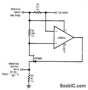
Ra senses output current of power supply. PN3684 JFET is used as buffer because source and drain currents arb equal, so monitor output voltage accurately refleets current flow of power supply.- FET Databook, National Semiconductor, Santa Clara, CA, 1977, p 6-26-6-36. (View)
View full Circuit Diagram | Comments | Reading(0)
Published:2009/7/14 3:35:00 Author:May

The tone-burst circuit puts out a 500-Hz tone, at a rate of 1 Hz, through an 8-Ω speaker, SPKR1. Besides the 9-V battery and its connecting snap, SPKR1 is the only non-surface-mount component in the circuit. The circuit can also be built from standard-size components. (View)
View full Circuit Diagram | Comments | Reading(814)
Published:2009/7/14 3:34:00 Author:May

Samples output of compute amplifier at end of each word, to provide d-c output for serial decoder and permit timesharing of computer amplifier. Full-scale output is -10 v d-c.-R. M. Centner and J. R. Wilkinson, New Approach to Serial Decoding. Eliminates Static Storage, Electronics, 35:34,p 32-35. (View)
View full Circuit Diagram | Comments | Reading(569)
Published:2009/7/14 3:34:00 Author:May

Used to control power oscillator of induction heater at rates up to 800 pps.-R. E. Mathews and F. R. Mathews and F.R.Sias, Jr., Testing Space Craft with Induction Heaters, Electronics, 35:34, p 38-41. (View)
View full Circuit Diagram | Comments | Reading(654)
Published:2009/7/14 3:34:00 Author:May

Combination of Motorola MC1408 DAC and MC1723 regulator gives digitally programmable voltages in 0.1-V increments at currents in excess of 100mA. Can be used as programmable lab power supply, computer-controlled supply for automatic test equipment, or in industrial control systems. Requires ±5 V and ±15V supplies. Voltage range can be increased to 25.5 V if positive supply is increased to 28.5 V or higher.-D. Aldridge and N. Wellenstein, Designing Digitally-Controlled Power Supplies, Motorola, Phoenix, AZ, 1975, AN-703, p 3. (View)
View full Circuit Diagram | Comments | Reading(953)
Published:2009/7/14 3:34:00 Author:May

Positive switching regulator circuit uses, μA732 with Unitrode PIC625 hybrid power switch and single transistor, operating in fixed OFF-time mode. Article covers regulator theory of operation in detail.-L. Dixon and ft. Patel, Designers' Guide to: Switching Regulators, EDN Magazine, Oct, 20, 1974, p 53-59. (View)
View full Circuit Diagram | Comments | Reading(714)
Published:2009/7/14 3:34:00 Author:May

Thyratron n pulse generator V1 produces voltage pulses of adjustable frequency for pulse shaper V2, which drives hydrogen thyatrons of high-power induction heater. V3 regulates repetition rate of pulses by acting as switch that, when conducting, allows C1 to discharge rapidly through R1.-H. L. Van Der Horst, How Radar Techniques Improve Induction Heating, Electronics, 32:7, P 51-55. (View)
View full Circuit Diagram | Comments | Reading(2616)
| Pages:642/2234 At 20641642643644645646647648649650651652653654655656657658659660Under 20 |
Response in 12 hours
© 2008-2012 SeekIC.com Corp.All Rights Reserved.