
Circuit Diagram
Index 654
LOGARITHMIC_PULSE_AMPIJFIER
Published:2009/7/15 22:56:00 Author:Jessie

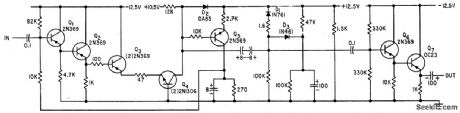
Selected series with D1 for straightening curvet give rent, from0.1 to100 ma.-D. Ophir ond U. zener diodes with breakdown voltages in dose approximation to logarithmic ampli- Galil, Zener Diode creates Logarithmic Pulse range of 4 to 6 v, with 1.6 ohm.resistor in fication of pulses over three decades of cur Amplifier, Electronics, 34:28, p 68-70. (View)
View full Circuit Diagram | Comments | Reading(743)
FET_REGENERATIVE_DETECTOR
Published:2009/7/15 22:56:00 Author:Jessie
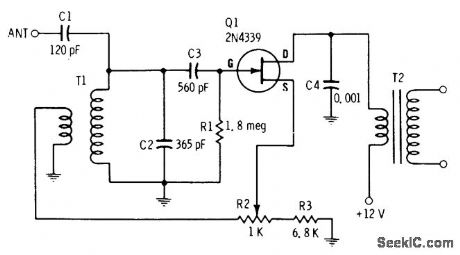
With 30-50 foot antenna wire, circuit gives sufficient volume for driving headphones connected to secondary of Lafayette AR-104 or equivalent audio driver transformer T2, for reception of broadcast stations when tuned over AM broadcast band with C2. Feedback control R2 is backed off slightly from point of oscillation, for maximum sensitivity in removing modulation from incoming carrier. When used for CW reception, circuit is left in oscillation and audible difference frequency is produced in output corresponding to marks and spaces. T1 is Miller 2004 or equivalent antenna transformer.-E. M. Noll, FET Principles, Experiments, and Projects, Howard W. Sams, Indianapolis, IN, 2nd Ed., 1975, p 235-237. (View)
View full Circuit Diagram | Comments | Reading(1195)
STEPPER_RELAY_RESET_AND_LATCH
Published:2009/7/15 22:55:00 Author:Jessie
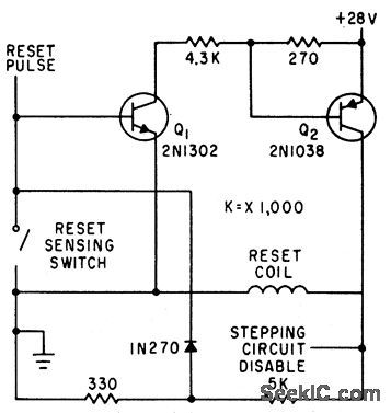
Reset circuit deenergizes lip-lop that controls coils of stepper relay, and provides latching to keep reset coil energized until wiper senses reset contact.-F. W. Kear, Coils Operate Stepping Relay at Higher Speed, Electronics, 35:6, p 60-63. (View)
View full Circuit Diagram | Comments | Reading(1327)
NEON_PHOTOCONDUCTOR_LATCHING_CIR_CUIT
Published:2009/7/15 22:54:00 Author:Jessie
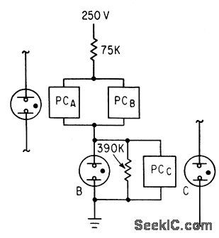
Cadmium sulfide photoconductor PC and Ne2H neon lamps give low-cost latch.When neon C is energized to provide input to PCA, neon B remains on, independent of input A, due to feedback from neon B to PCB. latch is reset by input to PCC.-J. L. Paterson, Will Neon Photoconductors Replace Relays in Low-Speed Logic?, Electronics, 36:18, p 46-49. (View)
View full Circuit Diagram | Comments | Reading(639)
THREE_STAGE_NEGATIVE_PULSEAMPLIFIER
Published:2009/7/15 22:53:00 Author:Jessie

Handles closely spaced negative pulses in radar beacon and similctr applications, with-amplifier stctge is inverse-feedback pair of triodes with out distortion and recovery problems.Each amplifier stage is inverse-feednback pair of triodes with 360 ° total phase shift.-R. E. Koncen, Wide-Range Multiple-Pulse Amplifier, Electronics, 33:38, p 78-81. (View)
View full Circuit Diagram | Comments | Reading(627)
PHOTOELECTRIC_LATCHING_RELAY
Published:2009/7/15 22:53:00 Author:Jessie
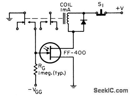
Photo-sensitive let serves as relay in light-activated smoke detectors, end-of-tape sensing in tape recorders, and light-activated alarms.-B. R. Smith, tight-Activated latching Relay, EEE, 14;8, p 167. (View)
View full Circuit Diagram | Comments | Reading(552)
TRANSISTORS_DRIVE_RELAY
Published:2009/7/15 22:52:00 Author:Jessie
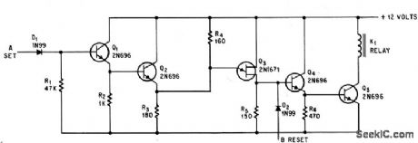
Relay latches on with +12 v set pulse ot A, and is unlatched by +12 v reset pulse at B.-S.E. Summer,Unijunction Tuansistor Latches Relay With Short Pulses,Electronics,38:9,p62.
(View)
View full Circuit Diagram | Comments | Reading(695)
A_C_STATIC_LATCHING_RELAY
Published:2009/7/15 22:50:00 Author:Jessie
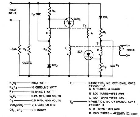
Is equivalent to single-pole electromechanical latching relay with electrically isolated solenoid. Once turned on, circuit remains in conducting state even though line voltage is interrupted for long periods of time. Positive reset action requires that minimum load current of 1 amp flow whenever circuit is closed.- Silicon Con-trolled Rectifier Manual, Third Edition, General Electric Co., 1964, p 106. (View)
View full Circuit Diagram | Comments | Reading(689)
THYRATRON_DRIVER
Published:2009/7/15 22:49:00 Author:Jessie
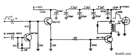
Input of 1 v makes solid-state circuit drive thyratron grid to 400 v within 60 nsec. Thyratron itself is fully on, and handling 100 amp al 6,000 v, in less than 100 nsec after input pulse. W. D. lsreal and W. B. McCartney, Nanosecond Thyratron Driver, EEE, 11:12, p 66. (View)
View full Circuit Diagram | Comments | Reading(1655)
REFLECTIVE_SENSOR
Published:2009/7/15 22:49:00 Author:Jessie
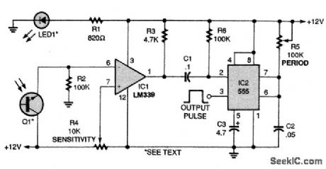
The IR sensor circuit shown produces an output when LED1's light is reflected from an object back to phototransistor Q1. The LED and phototransistor should be mounted parallel to each other and aimed in the same direction. Without a reflective object, the voltage at the input of the LM339 comparator (IC1) is at or near ground level and the output at pin 1 of IC1 is high. When the phototransistor detects a reflected light signal, the voltage at Q1's emitter goes high, causing the comparator's output to go low. The 555 timer (IC2) is then triggered, and produces a timed output pulse at pin 3. The circuit's sensitivity is set by R4 and its output time period by R5. Note that in this circuit, all of the unused input and output pins of the LM339 must be tied to circuit ground. (View)
View full Circuit Diagram | Comments | Reading(7981)
FOUR_STAGE_NEGATIVE_PULSE_AMPLIFIER
Published:2009/7/15 22:48:00 Author:Jessie

Gives gain of 87 db with over-all bandwidth of 0.9 Mc, using direct-coupled inverse-feed back pairs, for amplifying closely spaced pulse code groups coming from crystal detector of radar video receiver.-R. E. Koncen, Wide-Range Multiple-Pulse Amplifier, Electronics, 33:38, p 78-81. (View)
View full Circuit Diagram | Comments | Reading(601)
PRF_GENERATOR
Published:2009/7/15 22:48:00 Author:Jessie

Provides frequency stability of 3% as repetition rate generator in airborne radar. Free-running connections are shown, but may also be triggered externally.-NBS, Handbook Preferred Circuits Navy Aeronautical Electronic Equipment, Vol.1, Electron Tube Circuits, 1963, p N5-1. (View)
View full Circuit Diagram | Comments | Reading(844)
THREE_PHASE_OUTPUT_SIAGE
Published:2009/7/15 22:47:00 Author:Jessie
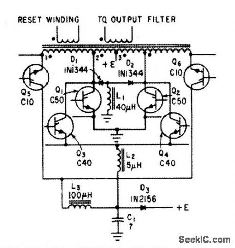
Scr's provide power switching for static inverter designed to develop 500 w of three-phase 115-v 400-cps power from input of 22 to 29 v d-c.-R. J. Kearns and J. J. Rolfe, Three-Phase Static Inverters Power Space-Vehicle Equipment, Electronics, 34:18, p 70-73. (View)
View full Circuit Diagram | Comments | Reading(825)
VIDEO_AMPLIFIER_WITH_TWONSEC_RISE_TIME
Published:2009/7/15 22:47:00 Author:Jessie

Uses feedback techniques with 1,000-Mc silicon lrcmsislors to give wide bandwidth and fast pulse response.-P. J. Beneteau and J. A Madntosh, Getting Fasl Pulse Response with Video Amplifers, Electronics, 34:41, p 62-63.
(View)
View full Circuit Diagram | Comments | Reading(780)
PROGRAMMABLE_CONTROLLER_PHOTOELECTRIC_INTERFACE
Published:2009/7/15 22:46:00 Author:Jessie

This circuit is an IR sensor with a timed positive output pulse that will operate with older and slower PLCs. Some of the early PLCs have scan times of 15 ms or more. The sensor's extended output pulse can be set, by R3, to a time period longer than the controller's scan time, The sensor can also be used as a stand-alone circuit to operate a counter, a valve, an indicator, or any other electrically controlled device. As long as nothing is blocking the IR light source, the emitter of phototransistor Q1 is high and 555 timer IC1 is set in the READY state. When an object blocks the light source, Q1 turns off, sending a negative pulse to the trigger input at pin 2 of IC1, producing a timed output pulse. R3, and C2, determine the length of the output pulse. Larger values produce longer output pulses. (View)
View full Circuit Diagram | Comments | Reading(836)
LADDER_TYPE_NETWORK_DECODER
Published:2009/7/14 2:45:00 Author:May

Transistor replaces spdt switch for binary conversion of analog signal. Transistor's own saturation voltage (shown as ground for simplicity) serves as lower reference, while diode provides upper reference. Chief drawback is poor temperature stability.-C. R. Pearman and A.E. Popodi, How to Design High-Speed D-A Converters, Electronics, 37:8, p 28-32. (View)
View full Circuit Diagram | Comments | Reading(734)
DUAL_TRIODE_DIFFERENIIAL_INVERTER
Published:2009/7/15 22:46:00 Author:Jessie
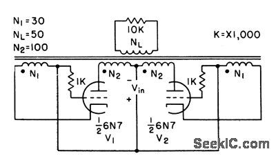
Uses electron tubes as switching elements in place of transistors. Although tubes are less efficient, availability of a suitable combination of voltage rating, current rating, and high-speed switching capacity may make tubes better than transistors in some signal or power converter applications.-C. H. R. Campling, Magnetic Inverter Uses tubes or Transistors, Electronics, 31:11, p 158-161. (View)
View full Circuit Diagram | Comments | Reading(483)
DIGITAL_ANALOG_CONVERTER
Published:2009/7/14 2:44:00 Author:May

Converts binary digits to analog form.-K,H. Brackney and D. R.Gosch, Pulse Comparator Circuit Measures Frequency Jitter,Elecytronics,34:27,p 54-56. (View)
View full Circuit Diagram | Comments | Reading(1216)
DIFFERENTIAL_MVBR_INVERTER
Published:2009/7/15 22:45:00 Author:Jessie
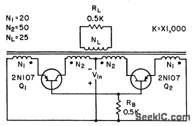
Magnetic inverter circuit with differentially connected windings oscillates reliably without use of current bias. Small spike in square-wave output can be eliminated by connecting small capacitor between collector and emitter of each transistor.-C. H. R. Campling, Magnetic Inverter Uses Tubes or Transistors, Electronics, 31;11, p 158-16l. (View)
View full Circuit Diagram | Comments | Reading(616)
INVERTER_AND_PULSE_STRETCHER
Published:2009/7/14 2:41:00 Author:May

Circuit likes sampled output of multiplexer and provides current required for driving transfluxor in analog-digital converter that produces six-bit binary Gray code.-N. Aron and C. Granger, Analog-To-Digital Converter Uses Transfluxors, Electronics, 35:20,p 62-66. (View)
View full Circuit Diagram | Comments | Reading(1577)
| Pages:654/2234 At 20641642643644645646647648649650651652653654655656657658659660Under 20 |
Circuit Categories
power supply circuit
Amplifier Circuit
Basic Circuit
LED and Light Circuit
Sensor Circuit
Signal Processing
Electrical Equipment Circuit
Control Circuit
Remote Control Circuit
A/D-D/A Converter Circuit
Audio Circuit
Measuring and Test Circuit
Communication Circuit
Computer-Related Circuit
555 Circuit
Automotive Circuit
Repairing Circuit