
Circuit Diagram
Index 1206
Oven_controlled_crystal_oscillator
Published:2009/7/24 7:56:00 Author:Jessie
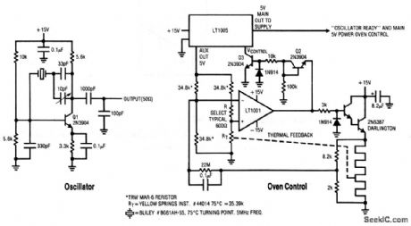
This circuit shows a Pierce-class oscillator with fine-frequency trimmer and an oven-control system. The LT1005 voltage regulator and the LT1001 op amp are used in a precision temperature-servo to control crystal temperature. Linear Technology Corporation, Linear Applications Handbook, 1990, p. AN12-3. (View)
View full Circuit Diagram | Comments | Reading(2241)
Crystal_oscillator_10_to_25_MHz
Published:2009/7/24 7:52:00 Author:Jessie

This circuit shows an LT1016 connected as an oscillator, which is suitable for operation in the 10- to 25-MHz range. Notice that the damper network (C=820 pF, R=22) prevents the AT-cut crystal from operating in the overtone mode. Linear Technology Corporation, Linear Applications Handbook, 1990, p. AN12-3. (View)
View full Circuit Diagram | Comments | Reading(725)
ACID_RAIN_MONITOR
Published:2009/7/1 0:54:00 Author:May
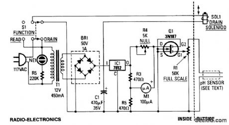
A bridge rectifier and 12-volt regulator powers the MOSFET sensing circuit. The unregulated output of the bridge rectifier operates the drain solenoid via switch S1. The sensor itself is built from two electrodes, one made of copper, the other of lead. In combination with the liquid trapped by the sensor, they form a miniature lead-acid cell whose output is amplified by MOSFET Q1. The maximum output produced by our prototype cell was about 50μA. MOSFET Q1 serves as the fourth leg of a Wheatstone bridge. When acidity causes the sensor to generate a voltage, Q1 turns on slightly, so its drain-to-source resistanc decreases.That resistance variation causes an imbalance in the bridge, and that imbalance is indicated by meter M1.
(View)
View full Circuit Diagram | Comments | Reading(0)
Crystal_oscillator_1_to_10_MHz
Published:2009/7/24 7:50:00 Author:Jessie
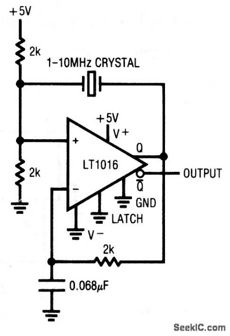
This circuit shows an LT1016, which is connected as an oscillator suitable for operation in the 1- to 10-MHz range. Linear Technology Corporaton, Linear Applications Handbook, 1990, p. AN12-3. (View)
View full Circuit Diagram | Comments | Reading(618)
INFRARED_TRANSMITTER
Published:2009/7/1 0:53:00 Author:May

The ultra-simple one-transistor, IR transmitter shown is designed to transmit the sound from any 8 or 16 ohm audio source, such as a TV, radio, or tape recorder on an infrared beam of light. (View)
View full Circuit Diagram | Comments | Reading(2180)
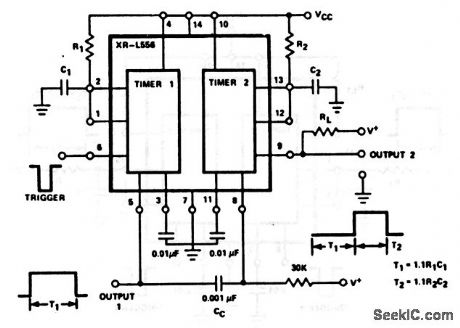
Micropower_oscillator_with_fixed_frequency_and_variable_duty_cycle_
Published:2009/7/24 7:13:00 Author:Jessie
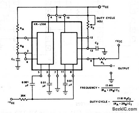
In this circuit, timer 1 is operated in the astable mode, and timer 2 is operated monostable; timer 1 triggers timer 2. The output (pin 9) has the same frequency as timer 1, but with a duty cycle determined by the timing cycle of timer 2. The output duty cycle can be adjusted from 1 to 99% by R2, typically a 10-kΩ potentiometer. EXAR Corporation Databook, 1990, p. 5-222. (View)
View full Circuit Diagram | Comments | Reading(804)
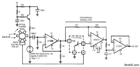
LOW_NOISE_INFRARED_DETECTOR
Published:2009/7/1 0:52:00 Author:May
View full Circuit Diagram | Comments | Reading(564)
Keyed_oscillator
Published:2009/7/24 6:03:00 Author:Jessie

In this circuit, one timer section of an XR-L556 is operated in the free-running mode, and is keyedon and off by the other section. The circuit output (timer 2) appears as a tone burst, whose frequency is set by RA, RB, and C2, and whose duration is set by R1 and C1. EXAR Corporation Databook, 1990, p. 5-222. (View)
View full Circuit Diagram | Comments | Reading(791)
Sequential_timing_delayed_one_shot
Published:2009/7/24 6:01:00 Author:Jessie
In this circuit, the output of one timer section triggers the other section so that the output of T2 is delayed from the initial trigger at pin 6 by a time delay of T1. Both T1 and T2 are set by values of external components, as shown. EXAR Corporation Databook, 1990 , p. 5-221. (View)
View full Circuit Diagram | Comments | Reading(629)
Independent_time_delay
Published:2009/7/24 6:00:00 Author:Jessie
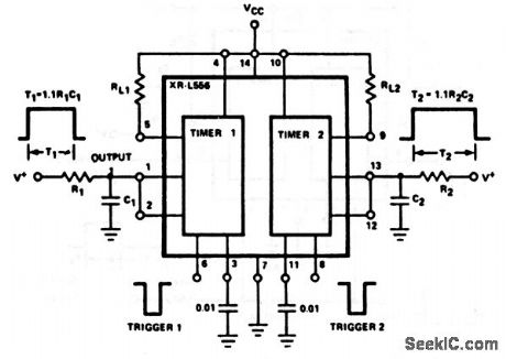
This circuit uses both sections of an XR-L556 dual timer to produce two independent time delays. Each section is used separately in the monostable mode to produce respective time delays T1 and T2. EXAR Corporation Databook, 1990 , p. 5-221. (View)
View full Circuit Diagram | Comments | Reading(606)
RELATIVE_HUMIDITY_SENSOR_SIGNAL_CONDITIONER
Published:2009/7/1 0:50:00 Author:May
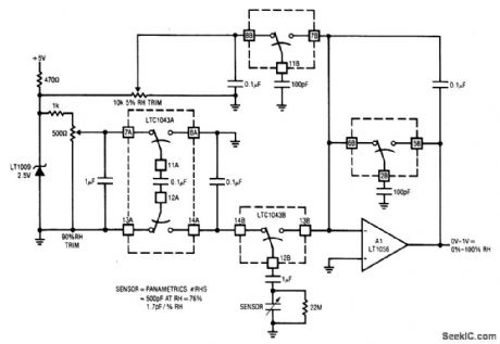
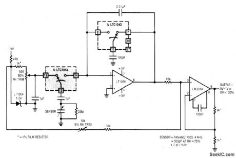
This circuit combines two LTC1043s with a based humidity transducer in a simple charge-pump based circuit. The sensor specified has a nominal 400 pF capacitance at RH = 76%, with a slope of 1.7 pF/% RH. The average voltage across this device must be zero. This provision prevents deleterious electrochemical migration in the sensor. The LTC1043A inverts a resistively scaled portion of the LT1009 reference, generating a negative potential at pin 14A. The LTC1043B alternately charges and discharges the humidity sensor via pins 12B, 13B, and 14B. With 14B and 12B connected, the sensor charges via the 1 pF unit to the negative potential at pin 14A. When the 14B-12B pair capacitor. Since the charge voltage is fixed, the average current into the summing point is determined by the sensor's humidity related value. The 1 μF value ac couples the sensor to the charge-discharge path, maintaining the required zero average voltage across the device. The 22M resistor prevents accumulation of charge, which would stop current flow. The average current into A1's summing point is balanced by packets of charge delivered by the switched-capacitor gives A1 an integrator-like response, and its output is dc. (View)
View full Circuit Diagram | Comments | Reading(2603)
Astable_free_running
Published:2009/7/24 5:59:00 Author:Jessie
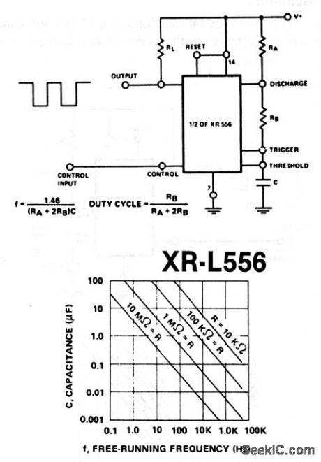
This circuit uses one section of an XR-L556 dual timer. Output frequency and duty cycle are set by C and R (Fig. 5-12B). Notice that R=RA + 2RB (Fig. 5-12B). EXAR Corporaton Databook, 1990, p. 5-218/5-221. (View)
View full Circuit Diagram | Comments | Reading(595)
DOOR_OPEN_ALARM
Published:2009/7/1 0:47:00 Author:May

Door open alarms are used chiefly in automotive, industrial, and appliance applications. This type of circuit can sense the opening of a refrigerator door. When the door opens, a triac could be activated to control the inside light. The figure shows a door position alarm. When the door is opened, an LED turns on and the piezo alarm sounds for approximately 5 seconds. This circuit uses a TL3019 Hall-effect device for the door sensor. This normally open switch is located in the door frame. The magnet is mounted in the door. When the door is in the closed position, the TL3019 output goes to logic low, and remains low until the door is opened. This design consists of a TLC555 monostable timer circuit. The 1 μF capacitor and 5.1 M ohm resistor on pins 6 and 7 set the monostable RC time constant. These values allow the LED and piezo alarm to remain on about 5 seconds when triggered. One unusual aspect of this circuit is the method of triggering. Usually a 555 timer circuit is triggered by taking the trigger, pin 2, low which produces a high at the output, pin 3. In this configuration with the door in the closed position, the TL3019 output is held low. The trigger, pin 2, is connected to IA the supply voltage Vgg. When the door opens, a positive high pulse is applied to control pin 5 through a 0.1 μF capacitor and also to reset pin 4. This starts the timing cycle. Both the piezo alarm and the LED visual indicator are activated. (View)
View full Circuit Diagram | Comments | Reading(2853)
ANGLE_OF_ROTATION_DETECTOR
Published:2009/7/1 0:45:00 Author:May

The figure shows two TL3103 linear Hall-effect devices used for detecting the angle of rotation. The TL3103s are centered in the gap of a U-shaped permanent magnet. The angle that the south pole makes with the chip face of unit #1 is defined as angle 0. Angle 0 is set to 0° when the chip face of unit #1 is perpendicular to the south pole of the magnet. As the south pole of the magnet sweeps through a 0° to 90°angle, the output of the sensor increases from 0°. Sensor unit #2 decreases from its peak value of +Vp at 0° to a value VOQ at 90°. So, the output of sensor unit #1 is a sine function of 0 and the output of unit #2 is a cosine function of 0 as shown. Thus, the first sensor yields the angle of rotation and the second sensor indicates the quadrant location. (View)
View full Circuit Diagram | Comments | Reading(1441)
Monostable_one_shot
Published:2009/7/24 5:57:00 Author:Jessie
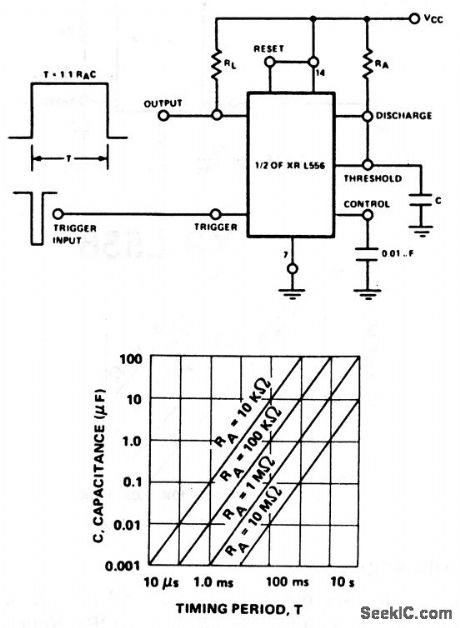
This circuit uses one section of an XR-L556 dual timer. Duration of the output pulse is set by C and RA (Fig. 5-11B). RL should equal the load being driven. EXAR Corporation Databook, 1990 , p. 5-218/5-220. (View)
View full Circuit Diagram | Comments | Reading(610)
Square_wave_oscillator
Published:2009/7/24 5:47:00 Author:Jessie
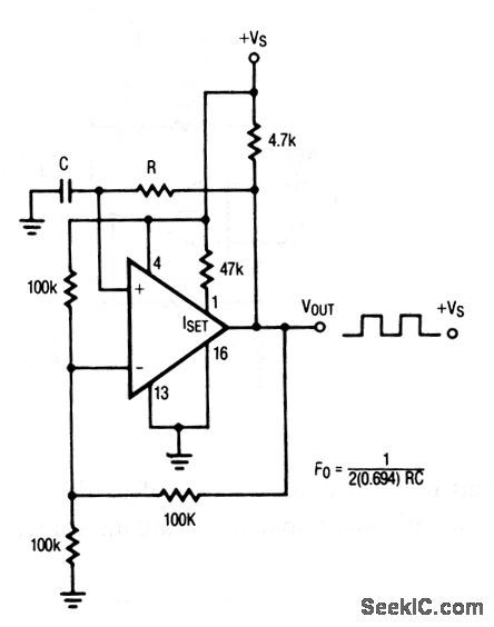
This circuit uses only one section of an LP165/365 comparator, and produces square waves at a frequency that is determined by the values of R and C, as shown. Raytheon Linear Integrated Circuts, 1989, p. 5-42. (View)
View full Circuit Diagram | Comments | Reading(1)
GAS_ANALYZER
Published:2009/7/1 0:43:00 Author:May
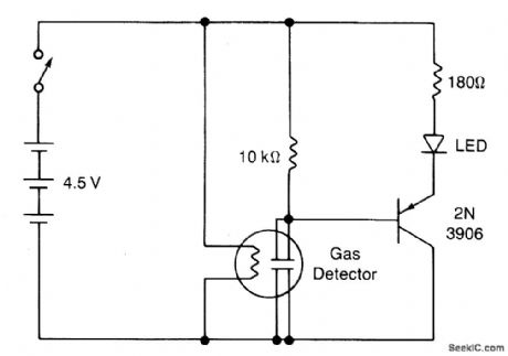
The circuit shows a simple yes/no gas detector. Three 1.5-V D cells are used as a power supply, with S1 acting as an on/off switch. The heater is energized directly from the battery, while the electrodes are in series with a 10 k resistor. The voltage across this resistor is monitored by a pnp transistor. When the sensor is in clean air, the resis-tance between the electrodes is about 40 k, so that only about 0.9 V is dropped across the 10 k resistor. This is insufftcient to turn on the transistor, because of the extra 1.6 V required to forward bias the light emitting diode (LED) in series with the emitter. When the sensor comes in contact with contaminated air, the resistance starts to fall, increasing the voltage dropped across the 10 k resistor. When the sensor resistance falls to about 10 k or less, the transistor starts to turn on, current passes through the LED, causing it to emit. The 180 ohm resistor limits the current through the LED to a safe value. (View)
View full Circuit Diagram | Comments | Reading(847)
Crystal_controlled_oscillator
Published:2009/7/24 5:46:00 Author:Jessie

This circuit uses only one section of an LP165/365 comparator,and produces pulses at 100 kHz using the values shown, with a single supply. Raytheon Linear Integrated Circuts, 1989, p. 5-42. (View)
View full Circuit Diagram | Comments | Reading(2157)
TOXIC_GAS_DETECTOR
Published:2009/7/1 0:41:00 Author:May
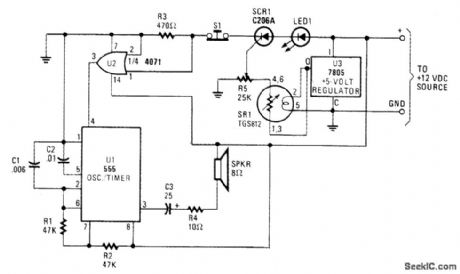
The major device in the circuit is SR1(a TGS812 toxic-gas sensor manufactured by Figaro Engineering Inc.) The gas-sensitive semiconductor (acting like a variable resistor in the resence of toxic gas) decreases in electrical resistance when gaseous toxins are absorved from the sensor surface. A 25,000 ohm potentiometer(R5) connected to thesensor serves as a load, voltage-dividing network, attd sensitivity control and has itscenter tap connected to the gate of SCR1,When toxic fumes come h contact with thesensor,decreasing its electrical resistance,current flows through the load (potentiometer R5).The voltage developed across the wiper of R5,which is connected to the gate of SCR1,triggers the SCR into conduction。With SCR1 now conducting,pin 1-volt Supplyfor the semiconductor elements of the TGS812 h1 spite of the suggested 10 volts,thusreducing the standby current.A 7805 regulator IS used to meet the 5-volt requlrementfor the heater and semiconductor elements. (View)
View full Circuit Diagram | Comments | Reading(5565)
WATER-LEVEL_INDICATOR
Published:2009/7/1 0:40:00 Author:May

In this a waming device WD1 is in series with SCR1. When the liquid level causes a conductive path between the probes, the SCR conducts sounding WD1. The waming device may be a Sonalert (TM), a lamp or a buzzer.D1 acts as a transient suppressor. Press S1 to reset the circuit.
(View)
View full Circuit Diagram | Comments | Reading(1116)
| Pages:1206/2234 At 2012011202120312041205120612071208120912101211121212131214121512161217121812191220Under 20 |
Circuit Categories
power supply circuit
Amplifier Circuit
Basic Circuit
LED and Light Circuit
Sensor Circuit
Signal Processing
Electrical Equipment Circuit
Control Circuit
Remote Control Circuit
A/D-D/A Converter Circuit
Audio Circuit
Measuring and Test Circuit
Communication Circuit
Computer-Related Circuit
555 Circuit
Automotive Circuit
Repairing Circuit