Position: Home > Circuit Diagram > Signal Processing > Micropower_oscillator_with_fixed_frequency_and_variable_duty_cycle_
Signal Processing
Micropower_oscillator_with_fixed_frequency_and_variable_duty_cycle_
Published:2009/7/24 7:13:00 Author:Jessie | From:SeekIC
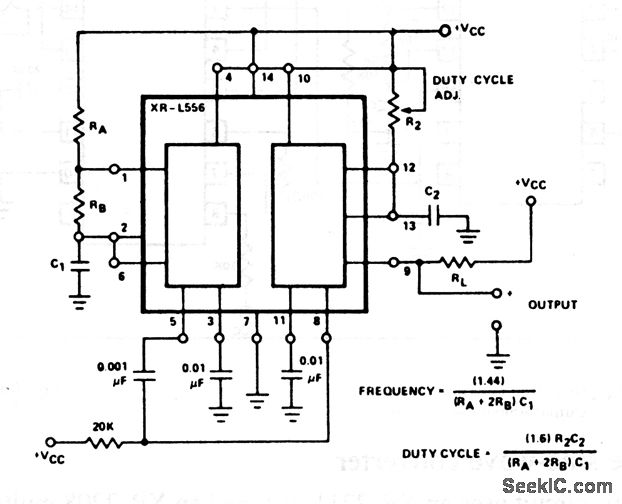
In this circuit, timer 1 is operated in the astable mode, and timer 2 is operated monostable; timer 1 triggers timer 2. The output (pin 9) has the same frequency as timer 1, but with a duty cycle determined by the timing cycle of timer 2. The output duty cycle can be adjusted from 1 to 99% by R2, typically a 10-kΩ potentiometer. EXAR Corporation Databook, 1990, p. 5-222.
Reprinted Url Of This Article:
http://www.seekic.com/circuit_diagram/Signal_Processing/Micropower_oscillator_with_fixed_frequency_and_variable_duty_cycle_.html
Print this Page | Comments | Reading(3)

Article Categories
power supply circuit
Amplifier Circuit
Basic Circuit
LED and Light Circuit
Sensor Circuit
Signal Processing
Electrical Equipment Circuit
Control Circuit
Remote Control Circuit
A/D-D/A Converter Circuit
Audio Circuit
Measuring and Test Circuit
Communication Circuit
Computer-Related Circuit
555 Circuit
Automotive Circuit
Repairing Circuit
Code: