Signal Processing
Astable_free_running
Published:2009/7/24 5:59:00 Author:Jessie | From:SeekIC

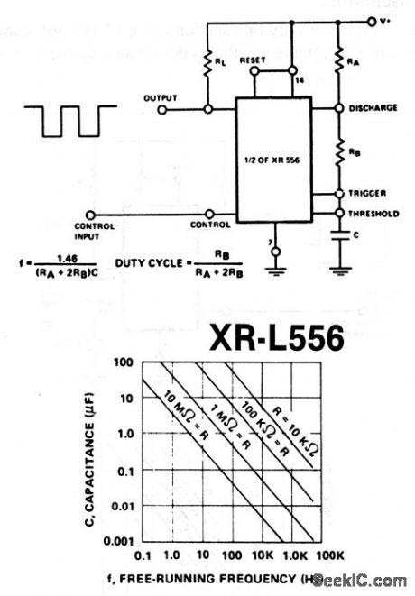
This circuit uses one section of an XR-L556 dual timer. Output frequency and duty cycle are set by C and R (Fig. 5-12B). Notice that R=RA + 2RB (Fig. 5-12B). EXAR Corporaton Databook, 1990, p. 5-218/5-221.
Reprinted Url Of This Article:
http://www.seekic.com/circuit_diagram/Signal_Processing/Astable_free_running.html
Print this Page | Comments | Reading(3)

Article Categories
power supply circuit
Amplifier Circuit
Basic Circuit
LED and Light Circuit
Sensor Circuit
Signal Processing
Electrical Equipment Circuit
Control Circuit
Remote Control Circuit
A/D-D/A Converter Circuit
Audio Circuit
Measuring and Test Circuit
Communication Circuit
Computer-Related Circuit
555 Circuit
Automotive Circuit
Repairing Circuit
Code: