
Circuit Diagram
Index 1215
Line_synchronous_clock_multivibrator_with_high_noise_immunity
Published:2009/7/24 9:16:00 Author:Jessie

This circuit uses an LT1011 to provide a line-synchronous clock that will not lose lock under very noisy line conditions. The basic RC multivibrator is tuned to free-run near 60 Hz, but the line-derived synchronizing input forces the oscillator to lock to the line. Noise rejection is obtained from the integrator characteristics of the RC network. Linear Technology, Linear Applications Handbook, 1990, p. AN31-12. (View)
View full Circuit Diagram | Comments | Reading(604)
5_mA_S_METER
Published:2009/6/30 21:31:00 Author:May

Circuit designed for 5-mA meter movement uses two-stage voltage ampilfer Q1-Q2 with emitter-follower output Q3 serving as impedance-matching stage AF input for S-9 reading is 25-30mV P-P and forfull scale is 50-60mV P-P Frequency response is 500 Hz to 10 kHz-M,A,Chapma,Solid-State S-Me-ters,Ham Radio,March 1975 p 20-23 (View)
View full Circuit Diagram | Comments | Reading(1142)
One_amplifier_one_shot_negative_output
Published:2009/7/24 9:16:00 Author:Jessie

This circuit uses one LM3900 Norton amplifier to provide a negative one-shot output pulse. CR1 (a 1N914 or equivalent) permits rapid re-triggering. National Semiconductor, Linear Applications Handbook, 1991, p. 243. (View)
View full Circuit Diagram | Comments | Reading(871)
3_state_battery_indicator
Published:2009/7/24 9:15:00 Author:Jessie

This circuit shows the state of a battery (typically 3V) by means of an LED and an ICL7665, The LED remains on if the battery voltage is above 2.8 V, and flashes if the battery voltage is between 2.35 and 2.8 V. The LED remains off if the battery voltage drops below 2.35V. (View)
View full Circuit Diagram | Comments | Reading(1587)
LEVEL_DETECTOR
Published:2009/6/30 21:29:00 Author:May

Circuit lights green LED if signal at output of audio preamp exceeds 1V peak for predetermined period. Red LED comes on when tone-control stage at output of preamp is on verge of clipping. VU meter driver circuit is also provided. Entire circuit must be duplicated for other stereo channel. Article describes drcuit operation in detail and gives all associated circuits used in high-performance audio preamp. D1 is 1N914; red LED is TIL209 or equivalent; green LED is TIL211.-D. Self, Ad.vanced Preamplifier Design, Wireless World, Nov. 1976, p 41-46. (View)
View full Circuit Diagram | Comments | Reading(0)
One_amplifier_one_shot_positive_output_
Published:2009/7/24 9:13:00 Author:Jessie

This circuit uses one LM3900 Norton amplifier to provide a positive one-shot output pulse. CR1 (a 1N914 or equivalent) permits rapid re-triggering. National Semiconductor, Linear Applications Handbook, 1991, p. 242. (View)
View full Circuit Diagram | Comments | Reading(895)
Combined_one_shot_and_comparator
Published:2009/7/24 9:12:00 Author:Jessie

This circuit uses two LM3900 Norton amplifiers to provide a one-shot output pulse only when the input exceeds a given value (0.8 V in this case). National Semiconductor, Linear Applications Handbook, 1991, p. 242. (View)
View full Circuit Diagram | Comments | Reading(775)
POSITIVE_INPUT_V_F_
Published:2009/6/30 21:28:00 Author:May
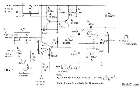
Input voltages from 0 to 10 V are divided by R1 and R2 for application to noninverting input of current source A1. 555 timer A2 provides functions of precision mono MVBR and level sensor.Regulator A3 acts as gated current source and provides stabilized voltage output for 555 and 308A.—W.G.Jung, IC Timer Cookbook, Howard W.Sams, Indianapolis, IN, 1977, p 184-192. (View)
View full Circuit Diagram | Comments | Reading(508)
1_mA_S_METER
Published:2009/6/30 21:27:00 Author:May

Amplifier designed for 1-mA meter movement consists of two-stage voltage amplifier driving meter rectifier. FET input provides high impedance to detected audio and minimizes loading and distortion problems. Q2 is common-emitter voltage amplifier with simple positive-pulse rectifier for meter. GI filters rectified audio signal. AF input for S-9 reading is 25-30 mV P-P and for full scale is 50-60 mV P-P Frequency response is 500 Hz to 10 kHz.-M A. Chapman, Solid-State S-Meters, Ham Fladio, March 1975, p 20-23. (View)
View full Circuit Diagram | Comments | Reading(2413)
LEDs_DISPLAY_VU_PEAKS
Published:2009/6/30 21:27:00 Author:May
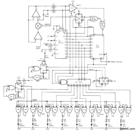
Exponential coding of Precision Monolithics DAC-76 D/A converter is used to good advantage in peak-reading VU indicator with logarithmic weighting, driving LED display, Input audio is converted by DAC-76,CMP-01 comparator,and 2502 successiveapproximation A/D converter after being sampled by sample-and-bold input circuit,A/D converter is clocked at 500kHz and completes conversion every 18μs,which is fast enough to track audio signals ,4 most significant magnitude bits drive 3205 1-of-8 decoder which is enabled by most significant bit,Resulting eight output levels,separated by 3-dB increments, drive 8-bit RS LATCH USING 74279 chips,updated every 25 ms hy 40-Hz display multiplex clock,-W.Jung and W.Ritmanich, Audio applicateions tof the DAC-76 Companding D/A Converter, Precision Monolithics,Santa Clara,CA 1977,AN-28, p 6 (View)
View full Circuit Diagram | Comments | Reading(566)
BIPOLAR_OUTPUT
Published:2009/6/30 21:24:00 Author:May


Low-cost voltage-to-fre-quency converter IC is here used in A/D converter circuit that will accept bipolar inputs and generate positive-going pulses to indicate positive input voltages and negative-going pulses for negative input voltages. Opamps A1 and A2 form negative-output absolute-value circuit that feeds opamp A3 and RC4151 voltage-to-frequency converter, for generating 10-μs negative-going pulses with repetition-rate scale factor of 1 kHz/V. Full-scale input is 20 V P-P.Opamp A4 is ground-referenced voltage comparator having zener clamp, providing TTL-compatible logic output for indicating input polarity. Pulse-receiver/decoder section takes digitally coded signals arriving from transmitter, for processing by data line or D flip-flop and two trigger inputs of dual-edge retriggerable mono MVBR This generates 25-μs negative-going output pulse for each 10-μs input pulse from data line. Logic 1 on complementary output of flip-flop indicates that original input voltage to transmitter was positive.—E. J.DeWath, Low-Cost A/D Converter Transmits and Receives, EDN Magazine, Jan. 5, 1977, p 35. (View)
View full Circuit Diagram | Comments | Reading(1015)
ADDING_S_METER
Published:2009/6/30 21:24:00 Author:May

Circuit works well with most all-band receivors.Q1 may also be SK3011,NR5, TR-10,or DS75.Q2 may also beHE1,SK-3005, or TR-06. Value of 1.2-megohm input resistor may need to be adjusted depending on AVC voltage,to prevent strong signals from overloading meter.- Novice Q & A, 73 Magazine, Feb 1977,p 127. (View)
View full Circuit Diagram | Comments | Reading(870)
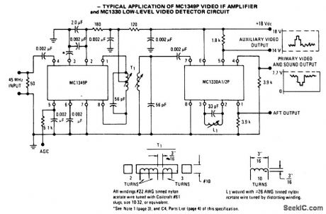
IF_AMPLIFIER
Published:2009/6/30 21:22:00 Author:May
View full Circuit Diagram | Comments | Reading(1539)
ADD_ON_S_METER
Published:2009/6/30 21:21:00 Author:May

Although designed for use with Clegg FM-27B 2-meter FM receiver, circuit can be readily adapted to other receivers. Am-plifier brings low-level455-MHz IF signal up to level suitable for driving meter. For other IF, such as 10.7 or 11.7 MHz, capacitor values should be changed accordingly. Any NPN tran, sistor with beta of 30 or more at IF value can be used. Diodes can be any type. Supply should be regulated but can be 7-14 V. Output of diode detector will vary from 0 to 1 V at nominal impedance of 20K; for best result, meter with 20- to 50-μA movement can be used.-M. Stern, FM-27B S-Meter, QST, Doc. 1976, p 35. (View)
View full Circuit Diagram | Comments | Reading(2446)
Digital_power_monitor_with_watchdog_timer_and_pushbutton
Published:2009/7/24 12:20:00 Author:Jessie
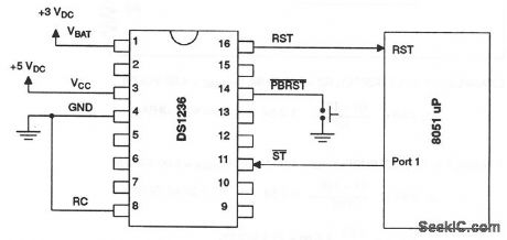
This circuit shows a DS1236 that is used to monitor and control the power-supply and software execution of a processor-based system, and to provide a pushbutton reset. When an out-of-tolerance condition occurs (when VCC is below 4.5 V for 10% operation, or below 4.75 V for 5% operation), the RST and RST outputs are driven to the active state. On power-up, RST and RST are held active for a minimum of 25 ms (100 ms typical) after 4.5 V (or 4.75 V) is reached to allow the power supply and processor to stabilize. The pushbutton input PBRST is debounced and timed so that reset signals are driven to the active state for 25 ms minimum. The watchdog-timer function forces RST and RST to the active state (shutting down the processor) when the ST input is not stimulated for a predetermined time period (because of some failure in software execution). The watchdog time period is 400-ms typical (600-ms maximum). The ST input can be taken from address, data, and/or control signals. When the processing is executing software, these signals are present, and cause the watchdog to be reset prior to time-out. Dallas Semiconductors, Product Data Book, 1992/1993, p. 10-73. (View)
View full Circuit Diagram | Comments | Reading(613)
Automatic_reset
Published:2009/7/24 12:16:00 Author:Jessie
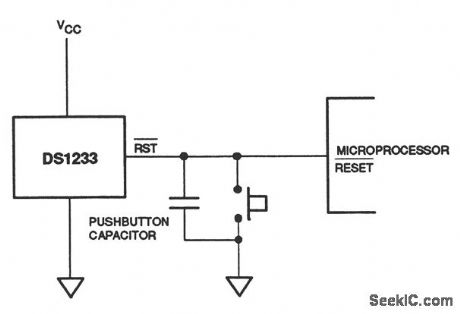
This circuit shows a DS1233 EconoReset chip that is used to monitor the power supply of a processor-based system and to provide automatic reset. The DS1233 contains a precision temperature-compensated reference and comparator circuit that is used to monitor the power-supply (VCC) status. When an out-of-tolerance condition is detected, RST becomes active, and shuts off the processor. When VCC returns to an in-tolerance condition, RST is kept in the active state for about 350 ms to allow the power supply and processor to stabilize. The DS1233 also debounces a pushbutton closure (when used), and generates a 350-ms reset pulse upon release. Notice that when an external pushbutton is used, a capacitor between 100 pF and 0.01μF must be connected between RST and ground. Where additional reset current is required, a minimum capacitance of 500 pF should be used, along with a parallel external pull-up 1-kΩ resistor (minimum). Dallas Semiconductors, Product Data Book, 1992/1993, p. 10-59. (View)
View full Circuit Diagram | Comments | Reading(720)
Low_power_micromonitor_with_pushbutton_and_watchdog_timer
Published:2009/7/24 12:13:00 Author:Jessie
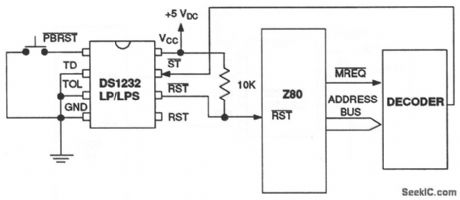
This circuit is similar to that of Fig. 6-50, but with the addition of a watchdog-timer function to monitor software execution. The timer function forces RST and RST signals to the active state (shutting down the processor) when the ST input is not stimulated for a predetermined time period (because of some failure in software execution). The time period is set by the TD input to be about 150 ms with TD connected to ground, 600 ms with TD left unconnected, and 1.2 s with TD connected to VCC . The timer starts timing out from the set-time period as soon as reset signals are inactive. The ST input can be taken from address, data and/or control signals. When the processor is executing software, these signals are present, which causes the watchdog to be reset prior to time-out. Dallas Semiconductors, Product Data Book, 1992/1993, p. 10-54. (View)
View full Circuit Diagram | Comments | Reading(692)
Low_power_micromonitor_with_pushbutton
Published:2009/7/24 12:09:00 Author:Jessie
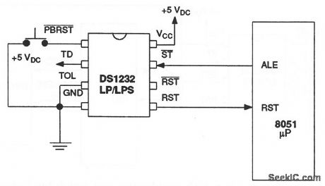
This circuit shows a DS1232LP/LPS used to monitor and control the power supply and software execution of a processor-based system, and to provide a pushbutton reset. When VCC falls below a preset level (as defined by the TOL pin connection) the DS1232 outputs RST and RST reset signals. With TOL connected to ground, reset becomes active as VCC falls below 4.75 V. When TOL is connected to VCC, reset becomes active as VCC falls below 4.5 V. On power-up, RST and RST are kept active for a minimum of 250 ms to allow the power supply and processor to stabilize. The pushbutton reset input PBRST requires an active low. Internally, this input is debounced and timed so that reset signals of at least 250 ms (minimum) are generated. The 250-ms delay starts as the pushbutton reset input is released from low level. Dallas Semiconductors, Product Data Book, 1992/1993, p. 10-54. (View)
View full Circuit Diagram | Comments | Reading(725)
Digital_power_monitor_that_operates_from_the_power_line
Published:2009/7/24 12:05:00 Author:Jessie
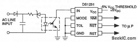
This circuit is similar to that of Fig. 6-47, except that the voltage sense point is taken directly from the ac power line, instead of from the power supply, and an optoisolator (chapter 9) is used between the line and DS1231. Dallas Semiconductors, Product Data Book, 1992/1993, p. 10-42. (View)
View full Circuit Diagram | Comments | Reading(511)
Digital_power_monitor_with_line_isolation
Published:2009/7/24 12:04:00 Author:Jessie
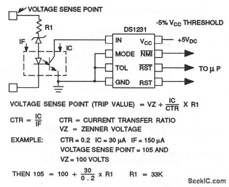
This circuit is similar to that of Fig. 6-47, except that an optoisolator (chapter 9) is used between the voltage sense point and the DS1231 to provide line isolation. Dallas Semiconductors, Product Data Book, 1992/1993, p. 10-41. (View)
View full Circuit Diagram | Comments | Reading(685)
| Pages:1215/2234 At 2012011202120312041205120612071208120912101211121212131214121512161217121812191220Under 20 |
Circuit Categories
power supply circuit
Amplifier Circuit
Basic Circuit
LED and Light Circuit
Sensor Circuit
Signal Processing
Electrical Equipment Circuit
Control Circuit
Remote Control Circuit
A/D-D/A Converter Circuit
Audio Circuit
Measuring and Test Circuit
Communication Circuit
Computer-Related Circuit
555 Circuit
Automotive Circuit
Repairing Circuit