Basic Circuit
Digital_power_monitor_with_watchdog_timer_and_pushbutton
Published:2009/7/24 12:20:00 Author:Jessie | From:SeekIC

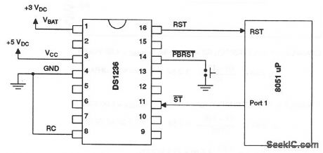
This circuit shows a DS1236 that is used to monitor and control the power-supply and software execution of a processor-based system, and to provide a pushbutton reset. When an out-of-tolerance condition occurs (when VCC is below 4.5 V for 10% operation, or below 4.75 V for 5% operation), the RST and RST outputs are driven to the active state. On power-up, RST and RST are held active for a minimum of 25 ms (100 ms typical) after 4.5 V (or 4.75 V) is reached to allow the power supply and processor to stabilize. The pushbutton input PBRST is debounced and timed so that reset signals are driven to the active state for 25 ms minimum. The watchdog-timer function forces RST and RST to the active state (shutting down the processor) when the ST input is not stimulated for a predetermined time period (because of some failure in software execution). The watchdog time period is 400-ms typical (600-ms maximum). The ST input can be taken from address, data, and/or control signals. When the processing is executing software, these signals are present, and cause the watchdog to be reset prior to time-out. Dallas Semiconductors, Product Data Book, 1992/1993, p. 10-73.
Reprinted Url Of This Article:
http://www.seekic.com/circuit_diagram/Basic_Circuit/Digital_power_monitor_with_watchdog_timer_and_pushbutton.html
Print this Page | Comments | Reading(3)

Article Categories
power supply circuit
Amplifier Circuit
Basic Circuit
LED and Light Circuit
Sensor Circuit
Signal Processing
Electrical Equipment Circuit
Control Circuit
Remote Control Circuit
A/D-D/A Converter Circuit
Audio Circuit
Measuring and Test Circuit
Communication Circuit
Computer-Related Circuit
555 Circuit
Automotive Circuit
Repairing Circuit
Code: