
Circuit Diagram
Index 1203
800_W_LIGHT_DIMMER
Published:2009/7/1 1:17:00 Author:May

This wide-range light dimmer circuit uses a unijunction transistor and a pulse transformer to provide phase control for the TRIAC. The circuit operates from a 115 volt, 60 Hz source and can control up to 800 watts of power to incandescent tights. The power to the lights is controlled by varying the conduction angle of the TRIAC from 0° to about 170°. The power available at 170°conduction is better than 9770 of that at the full 180°. (View)
View full Circuit Diagram | Comments | Reading(4351)
AUTOMATIC_LIGHT_CONTROLLER_FOR_CARPORT
Published:2009/7/1 1:15:00 Author:May

A 555 timer IC, operating in the one-shot mode, is triggered by light striking photoresistors. These normally have a resistance of several megohms but, in the pres-ence of light, that resistance drops to several hundred ohms, permitting current from the six-volt source to flow in the circuit. The R-C combination shown gives an on-time of about two minutes. Photoresistors PC3 and PC4 are mounted at heatlight-height. When headlights illuminate the photoresistor, the timer starts. That actuates a relay, RY1, and the lights are turned on. The lights are automatically turned off when the timer's two minutes are up. (View)
View full Circuit Diagram | Comments | Reading(921)
_5_to__5_V_at_220_mA_with_low_power_inverter
Published:2009/7/24 8:58:00 Author:Jessie

This circuit uses two transistors to buffer the LX output and produce 220-mA of output current. The 2N3904 is used invert the LX output and drive the power pnp. When using external transistor buffers as shown here, the output voltage is set by the external feedback-resistor network ( 180 and 510 kΩ). (View)
View full Circuit Diagram | Comments | Reading(604)
Crystal_oscillator_clock_circuits_for_digital_systems
Published:2009/7/24 8:58:00 Author:Jessie
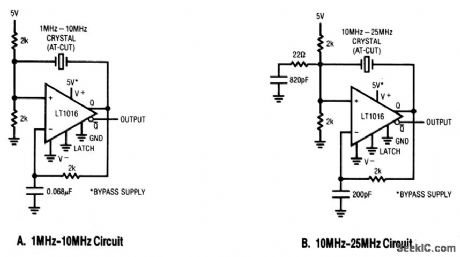
These two oscillator circuits cover the frequency range for most digital-system clock requirements. Linear Technology, Linear Applications Handbook, 1990, p. AN31-11. (View)
View full Circuit Diagram | Comments | Reading(594)
DC_LAMP_DIMMER
Published:2009/7/1 1:15:00 Author:May
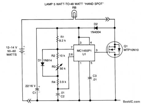
A low power, low cost dc lamp dimmer for a two-wire portable flashlight can be realized with little or no heatsinking. In addition, a single potentiometer, R3 adjusts lamp brightness.Battery power is stored in C1 for U1, which is a free-running multivibrator whose frequency is determined by R1, R2, R3, R4, and C2. U1 drives the gate of Q1, turning it and the lamp ON and OFF at a rate proportional to the multivibrator duty cycle. (View)
View full Circuit Diagram | Comments | Reading(6)
High_frequency_sine_wave_generator_with_quadrature_output
Published:2009/7/24 8:57:00 Author:Jessie
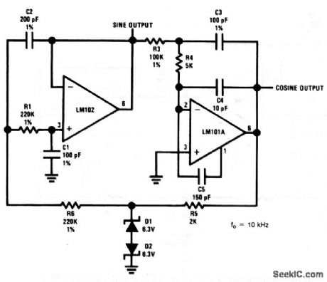
This circuit uses an LM102 and an LM101A to provide both a sine and cosine output at 10 kHz. National Semiconductor, Linear Applications Handbook, 1991, p. 84. (View)
View full Circuit Diagram | Comments | Reading(736)
Low_power_inverters
Published:2009/7/24 8:56:00 Author:Jessie


The table of Fig. 4-59B lists measured efficiency and currents of circuits that use the indicated coils and corresponding ICs. (View)
View full Circuit Diagram | Comments | Reading(669)
Low_power_step_down_converters
Published:2009/7/24 8:55:00 Author:Jessie


The table of Fig. 4-58B lists measured efficiency and currents of circuits that use the indicated coils. (View)
View full Circuit Diagram | Comments | Reading(543)
6_DIGIT_STOPWATCH
Published:2009/6/30 22:25:00 Author:May

Low-cost battery-pow-ered electronic stopwatch with 6-digit LED dis-play uses readily available complex-function CM0S ICs to minimize component count. Time range is up to 59 min and 59.99 s. Multiplexing by time-sharing counters through one display-driving decoder cuts battery drain because each digit is on for only one-sixth of time. Article traces operation of circuit step by step. Maxi-mum error is only 0.001 s/h. Four rechargeable nicad batteries Iast 500 h per charge if displays are blanked when not being read, and about 6 h without blanking.-A. Mouton, Build Your Own Digital Stopwatch with Strobed LED Read-out, EDN Magazine, AprilS, 1974, p 55-57. (View)
View full Circuit Diagram | Comments | Reading(3598)
Long_life_IR_drop_voltage_recover_system
Published:2009/7/24 8:53:00 Author:Jessie

This circuit provides a unique solution to a common system-level power-distribution problem. When the supply voltage to a remote board must traverse a long cable, the voltage at the end of the line sometimes drops to unacceptable levels. This circuit solves the problem by taking the reduced voltage at the end of the supply line and boosting it back to +5 V. This can be especially useful in remote-display devices, such as some point-of-sale (POS) terminals, where several meters of cable can separate the terminal from the readout. The 3.2: 1 turns ratio of the transformer allows the MAX631 to provide more than the usual output current, without an external MOSFET, at these relatively low operating voltages. Output current is 150mA at 5 V, with an input of 4 to 5 V. The MAX631 also makes use of the reflected voltage in the transformer primary to generate a higher supply voltage of about +9 V. By operating at 9 V, rather than 5 V, the on resistance of LX is reduced. (View)
View full Circuit Diagram | Comments | Reading(556)
Simple_boost_regulator
Published:2009/7/24 8:34:00 Author:Jessie

In this circuit,a MAX733 provides a+15-V output at 90 mA inputs from+4.5 to+12 V)or at 120 mA(for inputs from+6 to+12 V). (View)
View full Circuit Diagram | Comments | Reading(574)
Simple_buck_regulator_with_two_outputs
Published:2009/7/24 8:33:00 Author:Jessie

In this circuit, a MAX738 provides a +5-V 200-mA output through the inductor primary, and a + 12-V 30-mA output through the inductor secondary for inputs from 8 to 15 V . (View)
View full Circuit Diagram | Comments | Reading(777)
Simple_buck_regulator
Published:2009/7/24 8:31:00 Author:Jessie

In this circuit, a MAX730 provides a 5-V, 300-mA output for inputs from 6 to 10V . (View)
View full Circuit Diagram | Comments | Reading(548)
Simple_inverter_with_negative_output
Published:2009/7/24 8:30:00 Author:Jessie

In this circuit, a MAX739 current-mode PWM regulator provides all of the active circuitry needed to invert a positive input (+4 to +10 V) to a negative output (-5 V at 200 mA), with a minimum of external components. A switching frequency of 165-kHz allows for small external components. (View)
View full Circuit Diagram | Comments | Reading(658)
Low_frequency_sine_wave_generator_with_quadrature_output_1
Published:2009/7/24 8:28:00 Author:Jessie
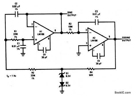
This circuit uses two LM108s to provide a both a sine and cosine output at 1 Hz. National Semiconductor, Linear Applications Handbook, 1991, p. 84. (View)
View full Circuit Diagram | Comments | Reading(772)
Tapped_inductor_buck_converter
Published:2009/7/24 8:28:00 Author:Jessie

This circuit uses a tapped inductor to increase the current output capability. The ratio of input turns to output turns is N. With an N of 3 (three times as many turns to the left of D 1 as at the right of D 1 ), a VIN of 20 V, an L of 100μH, and a VOUT of 5 V, the IOUT is approximately 10 A (double that of Fig. 4-39). (View)
View full Circuit Diagram | Comments | Reading(912)
Wien_bridge_sine_wave_oscillator
Published:2009/7/24 8:25:00 Author:Jessie

This circuit differs from other Wien-bridge oscillators described in this chapter only in the form of negative-feedback stabilization. Negative peaks in excess of -8.5 V cause D1 and D2 to conduct, which charges C4. The C4 charge biases Q1, which determines amplifier gain. C3 provides low-frequency roll-off in the feedback network, and prevents offset voltage/current errors from being multiplied. R5 is chosen to adjust the negative feedback loop so that Q1 is operated at a small negative gate bias. National Semiconductors, Linear Applications Handbook, 1991, p. 28. (View)
View full Circuit Diagram | Comments | Reading(1868)
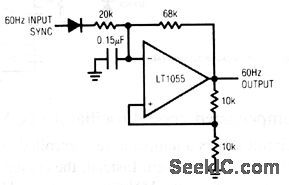
Stable_RC_oscillator
Published:2009/7/24 8:12:00 Author:Jessie


This circuit shows an RC clock circuit, which depends primarily on the RC elements for stability. The nominal-120-ppm/℃ temperature coefficient of the polystyrene capacitor is offset by the opposing positive temperature coefficient of the specified resistor. Linear Technology Corporation, Linear Appications Handbook, 1990, p. AN12-7. (View)
View full Circuit Diagram | Comments | Reading(693)
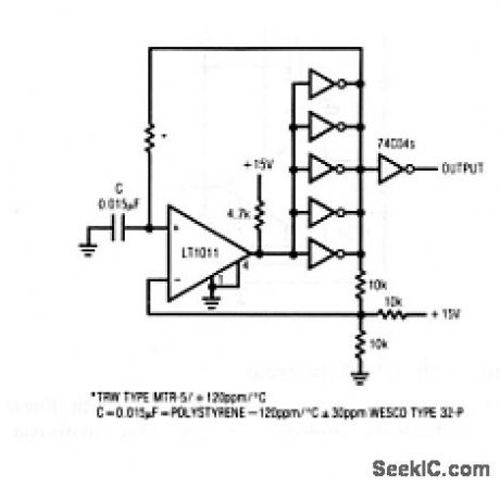
Reset_stabilized_oscillator
Published:2009/7/24 8:10:00 Author:Jessie

This circuit shows a synchronous clock generator, where the output locks at a higher frequency than the sync input. The maximum practical output-frequency to sync-frequency ratio is about 50 times. The output frequency is set to a multiple of the input frequency by the 5-kΩ Sync Adj pot. Linear Technology Corporation, Linear Applications Handbook, 1990, p. AN12-6. (View)
View full Circuit Diagram | Comments | Reading(508)
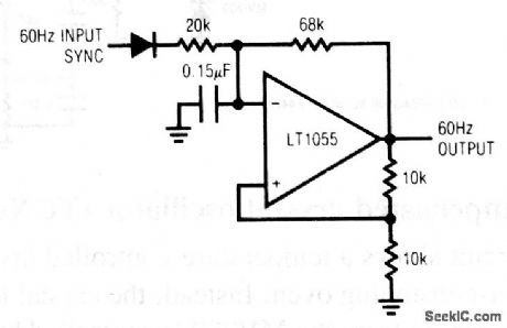
Synchronized_oscillator
Published:2009/7/24 8:08:00 Author:Jessie
This circuit shows a line-synchronized oscillator that will not lose lock under noisy line conditions. The circuit is suited to applications that require a reliable 60-Hz line-synchronous clock, and is superior to the usual zero-crossing detectors and simple voltage-level detectors. In this circuit, the basic RC multivibrator is tuned to free-run near 60 Hz, but the line-derived sync input forces the oscillator to lock on the ac line. Linear Technology Corporaton, Linear Applications Handbook, 1990, p. AN12-6. (View)
View full Circuit Diagram | Comments | Reading(1099)
| Pages:1203/2234 At 2012011202120312041205120612071208120912101211121212131214121512161217121812191220Under 20 |
Circuit Categories
power supply circuit
Amplifier Circuit
Basic Circuit
LED and Light Circuit
Sensor Circuit
Signal Processing
Electrical Equipment Circuit
Control Circuit
Remote Control Circuit
A/D-D/A Converter Circuit
Audio Circuit
Measuring and Test Circuit
Communication Circuit
Computer-Related Circuit
555 Circuit
Automotive Circuit
Repairing Circuit