Basic Circuit
Low_power_micromonitor_with_pushbutton
Published:2009/7/24 12:09:00 Author:Jessie | From:SeekIC

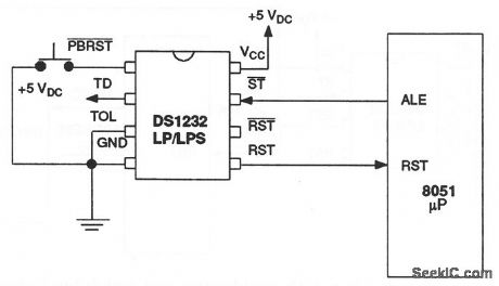
This circuit shows a DS1232LP/LPS used to monitor and control the power supply and software execution of a processor-based system, and to provide a pushbutton reset. When VCC falls below a preset level (as defined by the TOL pin connection) the DS1232 outputs RST and RST reset signals. With TOL connected to ground, reset becomes active as VCC falls below 4.75 V. When TOL is connected to VCC, reset becomes active as VCC falls below 4.5 V. On power-up, RST and RST are kept active for a minimum of 250 ms to allow the power supply and processor to stabilize. The pushbutton reset input PBRST requires an active low. Internally, this input is debounced and timed so that reset signals of at least 250 ms (minimum) are generated. The 250-ms delay starts as the pushbutton reset input is released from low level. Dallas Semiconductors, Product Data Book, 1992/1993, p. 10-54.
Reprinted Url Of This Article:
http://www.seekic.com/circuit_diagram/Basic_Circuit/Low_power_micromonitor_with_pushbutton.html
Print this Page | Comments | Reading(3)

Article Categories
power supply circuit
Amplifier Circuit
Basic Circuit
LED and Light Circuit
Sensor Circuit
Signal Processing
Electrical Equipment Circuit
Control Circuit
Remote Control Circuit
A/D-D/A Converter Circuit
Audio Circuit
Measuring and Test Circuit
Communication Circuit
Computer-Related Circuit
555 Circuit
Automotive Circuit
Repairing Circuit
Code: