Basic Circuit
Low_power_micromonitor_with_pushbutton_and_watchdog_timer
Published:2009/7/24 12:13:00 Author:Jessie | From:SeekIC

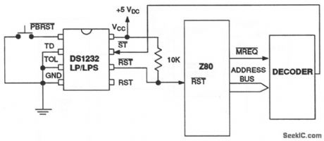
This circuit is similar to that of Fig. 6-50, but with the addition of a watchdog-timer function to monitor software execution. The timer function forces RST and RST signals to the active state (shutting down the processor) when the ST input is not stimulated for a predetermined time period (because of some failure in software execution). The time period is set by the TD input to be about 150 ms with TD connected to ground, 600 ms with TD left unconnected, and 1.2 s with TD connected to VCC . The timer starts timing out from the set-time period as soon as reset signals are inactive. The ST input can be taken from address, data and/or control signals. When the processor is executing software, these signals are present, which causes the watchdog to be reset prior to time-out. Dallas Semiconductors, Product Data Book, 1992/1993, p. 10-54.
Reprinted Url Of This Article:
http://www.seekic.com/circuit_diagram/Basic_Circuit/Low_power_micromonitor_with_pushbutton_and_watchdog_timer.html
Print this Page | Comments | Reading(3)

Article Categories
power supply circuit
Amplifier Circuit
Basic Circuit
LED and Light Circuit
Sensor Circuit
Signal Processing
Electrical Equipment Circuit
Control Circuit
Remote Control Circuit
A/D-D/A Converter Circuit
Audio Circuit
Measuring and Test Circuit
Communication Circuit
Computer-Related Circuit
555 Circuit
Automotive Circuit
Repairing Circuit
Code: