Sensor Circuit
RELATIVE_HUMIDITY_SENSOR_SIGNAL_CONDITIONER
Published:2009/7/1 0:50:00 Author:May | From:SeekIC


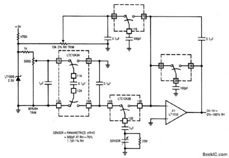
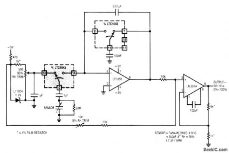
This circuit combines two LTC1043s with a based humidity transducer in a simple charge-pump based circuit. The sensor specified has a nominal 400 pF capacitance at RH = 76%, with a slope of 1.7 pF/% RH. The average voltage across this device must be zero. This provision prevents deleterious electrochemical migration in the sensor. The LTC1043A inverts a resistively scaled portion of the LT1009 reference, generating a negative potential at pin 14A. The LTC1043B alternately charges and discharges the humidity sensor via pins 12B, 13B, and 14B. With 14B and 12B connected, the sensor charges via the 1 pF unit to the negative potential at pin 14A. When the 14B-12B pair capacitor. Since the charge voltage is fixed, the average current into the summing point is determined by the sensor's humidity related value. The 1 μF value ac couples the sensor to the charge-discharge path, maintaining the required zero average voltage across the device. The 22M resistor prevents accumulation of charge, which would stop current flow. The average current into A1's summing point is balanced by packets of charge delivered by the switched-capacitor gives A1 an integrator-like response, and its output is dc.
Reprinted Url Of This Article:
http://www.seekic.com/circuit_diagram/Sensor_Circuit/RELATIVE_HUMIDITY_SENSOR_SIGNAL_CONDITIONER.html
Print this Page | Comments | Reading(3)

Article Categories
power supply circuit
Amplifier Circuit
Basic Circuit
LED and Light Circuit
Sensor Circuit
Signal Processing
Electrical Equipment Circuit
Control Circuit
Remote Control Circuit
A/D-D/A Converter Circuit
Audio Circuit
Measuring and Test Circuit
Communication Circuit
Computer-Related Circuit
555 Circuit
Automotive Circuit
Repairing Circuit
Code: